
help understanding narrowband wiring

Thread Starter
Registered User
Joined: Aug 2003
Posts: 2,925
From: Detroit
help understanding narrowband wiring
Ok i just installed a wideband in place of my passenger 02 and am "trying" to use the narrowband output wire to simulate the original.
The O2 connector has four wires... two for the heating element and two for the signal. Ive tapped into both the "low" and the "high" signal with my signal wire, but yet when logging in datamaster I only get a value of 450 across the board for that bank, while the other side is fluctuating around 800. The car is running TERRIBLE (in closed loop).
I dont understand why there are two signal wires. do i need to tap into both with my one signal wire? There isnt a narrowband plugged into the harness right now, so is the computer rejecting the data i am trying to send it by default?
The controller is calibrated properly for the output, and so is the wideband sensor.
help would be much appreciated. I am getting 8mpg right now. If i cant get this to work im going to yank the wideband back out for now until i can get a bung welded.

Registered User
Joined: Jul 2000
Posts: 993
From: Three Oaks MI
Ok i just installed a wideband in place of my passenger 02 and am "trying" to use the narrowband output wire to simulate the original.
The O2 connector has four wires... two for the heating element and two for the signal. Ive tapped into both the "low" and the "high" signal with my signal wire, but yet when logging in datamaster I only get a value of 450 across the board for that bank, while the other side is fluctuating around 800. The car is running TERRIBLE (in closed loop).
I dont understand why there are two signal wires. do i need to tap into both with my one signal wire? There isnt a narrowband plugged into the harness right now, so is the computer rejecting the data i am trying to send it by default?
The controller is calibrated properly for the output, and so is the wideband sensor.
help would be much appreciated. I am getting 8mpg right now. If i cant get this to work im going to yank the wideband back out for now until i can get a bung welded.
The O2 connector has four wires... two for the heating element and two for the signal. Ive tapped into both the "low" and the "high" signal with my signal wire, but yet when logging in datamaster I only get a value of 450 across the board for that bank, while the other side is fluctuating around 800. The car is running TERRIBLE (in closed loop).
I dont understand why there are two signal wires. do i need to tap into both with my one signal wire? There isnt a narrowband plugged into the harness right now, so is the computer rejecting the data i am trying to send it by default?
The controller is calibrated properly for the output, and so is the wideband sensor.
help would be much appreciated. I am getting 8mpg right now. If i cant get this to work im going to yank the wideband back out for now until i can get a bung welded.
Thread Starter
Registered User
Joined: Aug 2003
Posts: 2,925
From: Detroit
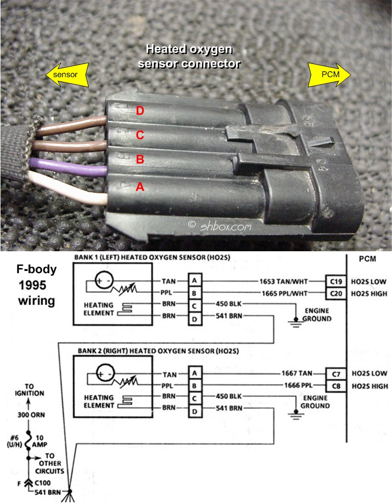
honestly im not sure about the ground. maybe its an obvious electric engineer symbol im not sure how to read (the squiggle perhaps?), here's the diagram from shoeboxes site:
Thread Starter
Registered User
Joined: Aug 2003
Posts: 2,925
From: Detroit
OK well i just figured that out on my own (duh)... one of the brown wires is in fact a ground. What should i be doing about that though?
I was thinking about plugging one of my old sensors in and just cutting the signal wires on it. But i still dont know which signal wire(s) i should be tapped into. Like i said ive had it on both so far.
I was thinking about plugging one of my old sensors in and just cutting the signal wires on it. But i still dont know which signal wire(s) i should be tapped into. Like i said ive had it on both so far.

Registered User
Joined: Feb 2008
Posts: 49
Ok well, from the diagram, it looks like the black wire (car side of the harness) is the ground, brown is the power for the heating element, neither of those deal with the sensing..
Then the top two wires are for high and low sensing, the bottom of the two sensing has what looks like a variable resistor on it, but I dont know what high and low side sensing is, all the o2 sensor's i've wires widebands into have been single wire ones, sorry
Then the top two wires are for high and low sensing, the bottom of the two sensing has what looks like a variable resistor on it, but I dont know what high and low side sensing is, all the o2 sensor's i've wires widebands into have been single wire ones, sorry
Thread Starter
Registered User
Joined: Aug 2003
Posts: 2,925
From: Detroit


Thread
Thread Starter
Forum
Replies
Last Post
dbusch22
Forced Induction
6
Oct 31, 2016 11:09 AM
Brandon Wittmer
General 1967-2002 F-Body Tech
3
Dec 3, 2014 09:28 PM
poloz28
Car Audio and Electronics
4
Sep 1, 2002 11:33 PM

