
Best prices you guys have seen for FAST\BIG STUFF 3

Registered User
Joined: Apr 2005
Posts: 1,546
From: Florence, Kentucky
Re: Best prices you guys have seen for FAST\BIG STUFF 3
What do you want to know?
It's an LS1 BS3 on an LT1. I'm running a 24X crank trigger, and the opti has been converted to a cam position sensor. Here's a pic of the converted opti.
The ignition is basically the LS1 truck coils (coil per cylinder).
For good points vs. bad points, I chose the BS3 because I feel it's the best on the market. It has features that none of the others have, and I think it's the best setup for a engine management system that references boost.
2. Where is the Crank Trigger located? Where do I get parts for it?
3. Did you have to buy a LTCC converter box or does the BS3 run the LS1 coils directly?
4. Basically I want to know how to adapt a BS3 that was made for the LS1 to an LT1.
Thanks for the help in advance.


Registered User
Joined: Sep 1999
Posts: 393
From: NASHVILLE, TN
Re: Best prices you guys have seen for FAST\BIG STUFF 3
Do you have a pic of the 24X crank trigger? and where did you get?
I'm trying to do the same thing.... LS1 BS3 on a LT1 with coilpacks.


Registered User
Joined: Mar 2005
Posts: 849
From: Shawnee Kansas
12v square wave covering 4 cylinders or one crank rotation.
I don't know what cylinders are on/off.
From GMeSI:
The Camshaft Position sensor is mounted through the top of the engine block at the rear of the valley cover and works in conjunction with a 1X reluctor wheel on the camshaft. The reluctor wheel is inside the engine immediately in front of the rear cam bearing. The PCM provides a 12 volt power supply to the CMP sensor as well as a ground and a signal circuit.
The PCM uses the Camshaft Position sensor in order to determine whether a cylinder is on a firing or exhaust stroke. The reluctor wheel interrupts a magnetic field produced by a magnet within the CMP sensor as the camshaft rotates. The CMP sensor's internal circuitry detects this and produces a signal which is the PCM reads. The PCM uses this 1X signal in combination with the Crankshaft Position sensor 24X signal in order to determine the crankshaft position and stroke. This diagnostic for the Camshaft Position sensor checks for a loss of Camshaft Position sensor signal. The PCM also monitors the CMP sensor signal circuit for malfunctions. The following DTCs set when the PCM detects a CMP sensor that is out of the normal operating range.
DTC P0341 Camshaft Position Sensor (CMP) Circuit Performance.
DTC P0342 Camshaft Position Sensor (CMP) Circuit Low Voltage.
DTC P0343 Camshaft Position Sensor (CMP) Circuit High Voltage.
Registered User
Joined: Mar 2005
Posts: 849
From: Shawnee Kansas
I got more:
The Camshaft Position (CMP) sensor is mounted through the top of the engine block at the rear of the valley cover. The CMP sensor works in conjunction with a 1X reluctor wheel on the camshaft. The reluctor wheel is inside the engine immediately in front of the rear cam bearing. The PCM provides a 12 volt power supply to the CMP sensor as well as a ground and a signal circuit.
The CMP sensor determines whether a cylinder is on a firing stroke or on an exhaust stroke. As the camshaft rotates, the reluctor wheel interrupts a magnetic field produced by a magnet within the sensor. The sensors internal circuitry detects this and produces a signal which the PCM reads. The PCM uses this 1X signal in combination with the Crankshaft Position (CKP) sensor 24X signal in order to determine crankshaft position and stroke. This diagnostic monitors for a loss of Camshaft Position sensor signal.
Observe that as long as the PCM receives the Crankshaft Position sensor 24X signal, the engine will start. The PCM can determine top dead center for all cylinders by using the Crankshaft Position sensor 24X signal alone. The Camshaft Position sensor 1X signal is used by the PCM to determine if the cylinder at top dead center is on the firing stroke, or the exhaust stroke. The system attempts synchronization and looks for an increase in engine speed indicating the engine started. If the PCM does not detect an increase in engine speed, the PCM assumes it incorrectly synchronized to the exhaust stroke and re-syncs to the opposite cam position. A slightly longer cranking time may be a symptom of this condition.
Conditions for Running the DTC
The engine speed is less than 4,000 RPM.
Conditions for Setting the DTC
The PCM detects that a CMP to CKP mis-match has occurred for 10 seconds.
Action Taken When the DTC Sets
The PCM illuminates the malfunction indicator lamp (MIL) on the second consecutive ignition cycle that the diagnostic runs and fails.
The PCM records the operating conditions at the time the diagnostic fails. The first time the diagnostic fails, the PCM stores this information in the Failure Records. If the diagnostic reports a failure on the second consecutive ignition cycle, the PCM records the operating conditions at the time of the failure. The PCM writes the conditions to the Freeze Frame and updates the Failure Records.
Conditions for Clearing the MIL/DTC
The PCM turns OFF the malfunction indicator lamp (MIL) after 3 consecutive ignition cycles that the diagnostic runs and does not fail.
A last test failed, or current DTC, clears when the diagnostic runs and does not fail.
A history DTC clears after 40 consecutive warm-up cycles, if no failures are reported by this or any other emission related diagnostic.
Use a scan tool in order to clear the MIL and the DTC.
Diagnostic Aids
Important
Remove any debris from the PCM connector surfaces before servicing the PCM. Inspect the PCM connector gaskets when diagnosing/replacing the PCM. Ensure that the gaskets are installed correctly. The gaskets prevent contaminant intrusion into the PCM.
For any test that requires probing the PCM or component harness connectors, use the J 35616-A connector test adapter kit . Using this kit prevents any damage to the harness connector terminals. Refer to Using Connector Test Adapters in Wiring Systems.
The following conditions may cause this DTC to set:
Poor connections: Refer to Testing for Intermittent and Poor Connections in Wiring Systems.
Camshaft reluctor wheel damage.
The sensor coming in contact with the reluctor wheel.

Registered User
Joined: Dec 2002
Posts: 603
From: Bethel Pa.
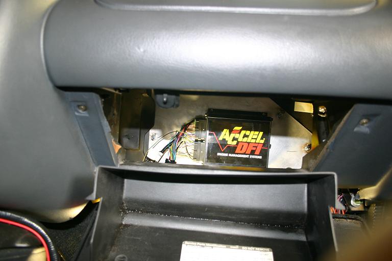
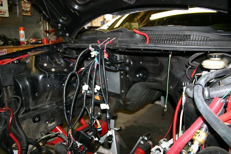
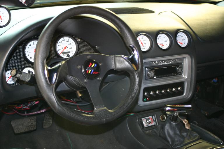
I had went with a DFI system on mine, I decided to get rid of everything I didnt need, I got a full LT1 kit that came with a new wireing harness, its a kit thats made to install a LT1 into a diffrent car, my AC is gone, and I made a custom gauge cluster so everything still works so I could get rid of the factory PCM and wireing on there.

Thread
Thread Starter
Forum
Replies
Last Post
ChrisFrez
CamaroZ28.Com Podcast
0
Nov 30, 2014 08:41 AM
bossco
Automotive News / Industry / Future Vehicle Discussion
4
Nov 29, 2014 10:18 AM