
Intake restrictions. How to diagnose.


Registered User
Joined: Feb 2004
Posts: 4,800
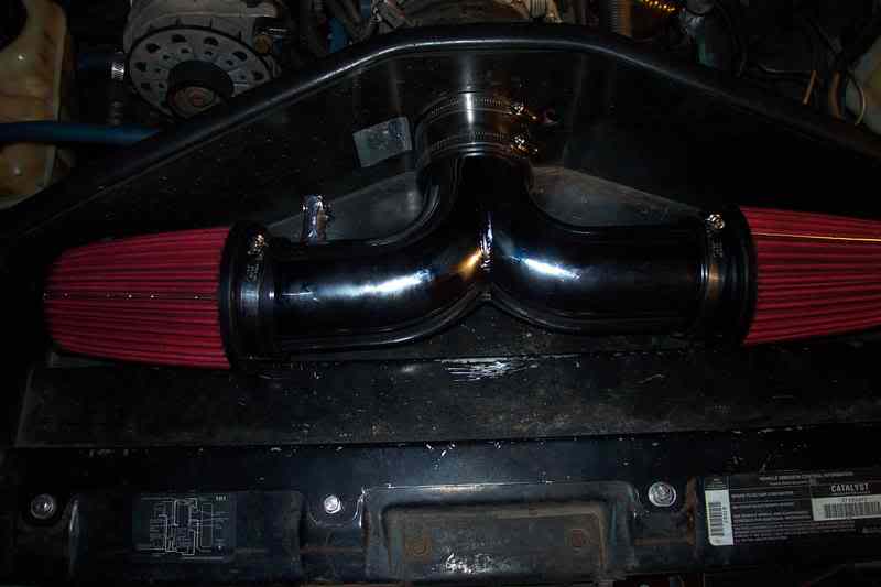
Like I said on the other forum. I see similar KPA values with this intake, stock f-body MAF and 58mm TB. The y-pipe is 3.5", this is pretty short and direct. The filters are not huge but there are two and they have the inverted cones in the end so combined that should be a sufficient capacity.
I forget if it was this board or the other where someone suggested the MAP location might give a false low KPA number. I at least found that to be an interesting idea. Would be interesting to use a length of hose and try and connect the MAP to one of the other vaccuum ports. Of course you would have to plug the existing hole.
I just don't believe that a setup this open is costing me the kind of power being discussed here. 1kpa is certainly about 1% pressure but I don't think that means 1% volume which is what would cost you 1% power. Like I said too I don't think equal numbers is all that realistic either, at least not on an engine actually moving air with this MAP location and intake. http://en.wikipedia.org/wiki/Bernoulli's_principle

Registered User
Joined: Apr 2008
Posts: 404
From: College Station, Tx
my set up is the same as the person with the pinches. And my KPA is good. I used a 3.5" rubber hose with a 3" PVC coupling to mount the filter to it. A lot easier to work with that that moroso crap i had.
Thread Starter
Registered User
Joined: Aug 2005
Posts: 4,405
From: Kantuckee Yo'
How did you determine your KPA is good or rather that you have minimal preesure drop?
Registered User
Joined: Feb 2004
Posts: 4,800
If it is not making any power then Bernoulli's principle would not come into play much. An engine making power with the MAP located such as it is could get a false reading because of this though.
Administrator
Joined: Nov 1998
Posts: 71,112
From: Hell was full so they sent me to NJ
MAP (along with absolute temperature) determines the mass of air in the cylinder. Mass = volume x density. Volume of the cylinder is fixed. Only the density can vary, The higher the absolute pressure, the higher the density of the air. Decrease MAP by 1% and the density changes, not the volume. The larger the mass of air, the more fuel you can burn = more HP. The speed-density concept is based on this. That's how the ECM calculates the mass of air in the engine.... by looking at the density of the air in the plenum.
Remember also that you continue to lose pressure as the air flows through the intake runners. By the time it gets to the cylinders, its lost a few more kPa. That extra kPa in the plenum may be worth even more than 1%, since the 1% is based on losing 1kPa out of 101.
It would appear they tried to locate the MAP sensing point in the "corner" of the plenum, where it would not be subject to the Bernoulli effect. Whether they succeded is not determined.

Registered User
Joined: Feb 2004
Posts: 4,800
Fred you are right I should have said density not volume.
Part of what I am arguing here is that a stock/weak setup may not experiance the Bernoulli effect while a setup moving air could.
Why else would twcblackhand6970 see so much less vaccuum than I do? My setup might not be perfect but it is fairly open.
Part of what I am arguing here is that a stock/weak setup may not experiance the Bernoulli effect while a setup moving air could.
Why else would twcblackhand6970 see so much less vaccuum than I do? My setup might not be perfect but it is fairly open.
Registered User
Joined: Apr 2008
Posts: 404
From: College Station, Tx
yea, car has stock heads and those data runs are with stock cam. once I get the car back with the 306, I'll get you those numbers to see if they change at all.
by the way, what exactly is the bernoulli effect?
by the way, what exactly is the bernoulli effect?
Registered User
Joined: Oct 2001
Posts: 1,517
From: Engineerland
Like I said before I think the pull from the two runners located almost directly under the map probably causes alot of the problem. When you begin to really move alot of air 350-400g/sec the pull and high velocity low pressure region from the ports has to become farther reaching into the intake. When the cylinder and the intake system are relatively the same size and you go from an 80% ve to 105-110% ve at the same rpm the velocity cannot help but increase. You'll have to pardon my wording here (did not elect to take a cfd class) but the 'gulp' of air that the cylinder takes in is also larger by definition with the increased ve. Nature being the way she is hates a vacuum and gets the air from wherever there is pressure. I believe this accounts for the pulsing I see in the map signal during runs. My map oscillates during the upper end of the run between 85-90kPa pretty sharply sometimes worse nearing 7000rpm. In the first part of the run its fine stable as can be with maybe 98kPa pretty much. Vacuum gauge backs up the map sensor as far as showing the vacuum but the gauge is damped and my eye isnt fast enough to see the oscillations in it anyways. In order to see the pulsing you have to get into at least the 280's for aiflow to see it looking at some of the datamaster logs I have here.
If somebody had a spare map sensor they could leave the one they are using in place and make a simple bracket to hold the second one and hook into a vacuum portand move the electrical harness over to it and see what the result is.
I'll see if I can find a good log that shows it to screenshot and post then i'll export the data and screenshot that too. so you guys can see the numbers vs the graph. Might take awhile to find in a freescan log (it takes records at a faster rate).
Registered User
Joined: Oct 2001
Posts: 1,517
From: Engineerland
Basicly the easiest way to explain it is with the engineering equation that came from it using a nozzle (think parking cone). Now the fluid (air) has two types of energy pressure and velocity. At the big end of the nozzle the velocity is low and the pressure is high at the small end the velocity is high and the pressure is low. The changes are directly related, in other words it turns the pressure head into velocity head. This is the same basic principle used to create lift in aircraft. Pretty much, high velocity fluids have a resulting pressure drop.
Administrator
Joined: Nov 1998
Posts: 71,112
From: Hell was full so they sent me to NJ
A simple explanation... air moving perpendicular to a tube causes a reduced pressure (= vacuum) in the tube. As velocity increases, the vacuum increases. If the horizontal stream of air entering through the throttle body bore is passing directly under the verticall tube that forms the MAP sensor opening to the manifold, the pressure in the tube will be less than it would be if it was in a stagnent flow area. Another example of the Bernoulli effect it the fact that exhaust gasses moving rapidly past a gap in the exhaust will cause a reduced pressure at the gap, and actually educt (= suck) air into the exhaust stream.
If you think about it, most high flow engines will have a larger throttle body. Might put the flow stream closer to the MAP location.
I pulled up one of my MoTeC data logs, for an NA run. There was definitley a "pulsing" in the MAP readings, on about a 0.05 second frequency at RPM above 5,000.
3,500rpm - 102.2kPa
4,000 - 101.2
5,000 - 102.1
First pulse appeared, with 0.05 second interval (data logging was ~ 20 frames per second)
5,129 - 96.5
5,173 - 100.7
5,274 - 100.2
Another drop over 0.05 sec
5,381 - 98.2
5,963 - 103.0
6,000 - 100.0
6,459 - 99.4
6,642 - 99.0
6,744 - 100.0
another drop after 0.05 sec
6,808 - 96.86
7,001 - 96.2
6,907 - 100.1
0.05 seconds
6,943 - 95.2
7,093 - 97.5
7,114 - 96.2
At the end of the above, those are sequential data points. Earlier data over a larger RPM gap are just selected to cover the range fro 3,500 - 6,500rpm.
As a reference point, my intake track consists of a stock WS6 hood with all baffles cut out, a stock WS6 airbox with the cover cut fully open, a K&N panel filter, no MAF (3" silicon tube in place of MAF), a 3" smooth Fernco sewer pipe connector to the throttle body, 58mm TB, 58mm intake bores.


The reason you don't see the fluctuations on your vacuum gauge, assuming its a mechanical gauge, run off a long hose to the intake, is because the length of the hose dampens the pressure pulsation. Attaching a spare MAP sensor to a vacuum nipple would introduce the same dampening of the pulses, depending on the length of the hose. Additionally, who's to say that the vacuum nipple connection to the inside of the intake plenum isn't directly over a runner for one of the cylinders, possibly increasing the Bernoulli effect?
Another thing to take into consideration. As the vehicle speed increases, the pressure of the air on the face of the vehicle increases.... velocity head principle. That increases the pressure at a hood scoop, if the scoop is not in the "calm" area that clings to the surface of the hood once you get much past the nose of the bumper. That "ram air" effect should show up as increased pressure in the plenum. How much of the velocity head ends up in the plenum will be a function of the shape of the hood opening, the contour of the opening as it passes through the hood, how well the hood is sealed to the airbox, etc.
If you think about it, most high flow engines will have a larger throttle body. Might put the flow stream closer to the MAP location.
I pulled up one of my MoTeC data logs, for an NA run. There was definitley a "pulsing" in the MAP readings, on about a 0.05 second frequency at RPM above 5,000.
3,500rpm - 102.2kPa
4,000 - 101.2
5,000 - 102.1
First pulse appeared, with 0.05 second interval (data logging was ~ 20 frames per second)
5,129 - 96.5
5,173 - 100.7
5,274 - 100.2
Another drop over 0.05 sec
5,381 - 98.2
5,963 - 103.0
6,000 - 100.0
6,459 - 99.4
6,642 - 99.0
6,744 - 100.0
another drop after 0.05 sec
6,808 - 96.86
7,001 - 96.2
6,907 - 100.1
0.05 seconds
6,943 - 95.2
7,093 - 97.5
7,114 - 96.2
At the end of the above, those are sequential data points. Earlier data over a larger RPM gap are just selected to cover the range fro 3,500 - 6,500rpm.
As a reference point, my intake track consists of a stock WS6 hood with all baffles cut out, a stock WS6 airbox with the cover cut fully open, a K&N panel filter, no MAF (3" silicon tube in place of MAF), a 3" smooth Fernco sewer pipe connector to the throttle body, 58mm TB, 58mm intake bores.
The reason you don't see the fluctuations on your vacuum gauge, assuming its a mechanical gauge, run off a long hose to the intake, is because the length of the hose dampens the pressure pulsation. Attaching a spare MAP sensor to a vacuum nipple would introduce the same dampening of the pulses, depending on the length of the hose. Additionally, who's to say that the vacuum nipple connection to the inside of the intake plenum isn't directly over a runner for one of the cylinders, possibly increasing the Bernoulli effect?
Another thing to take into consideration. As the vehicle speed increases, the pressure of the air on the face of the vehicle increases.... velocity head principle. That increases the pressure at a hood scoop, if the scoop is not in the "calm" area that clings to the surface of the hood once you get much past the nose of the bumper. That "ram air" effect should show up as increased pressure in the plenum. How much of the velocity head ends up in the plenum will be a function of the shape of the hood opening, the contour of the opening as it passes through the hood, how well the hood is sealed to the airbox, etc.
Last edited by Injuneer; Mar 15, 2009 at 12:27 AM.
Registered User
Joined: Oct 2001
Posts: 1,517
From: Engineerland
My mechanical gauge is damped because I drilled and tapped it with a small restriction, it was much too sensitive as delivered. But yes the hose also serves to damp it. I think the big issue is though, that the pulsing is happening lets say from cylinder 2 and 4 at 6000rpm thats pretty fast for the human eye much less a cheap mechanical mechanism to pick up... its even pretty fast for 20 frames a second. It'd be nice to have data aquisition and instrumentation that was lab quality and would sample that fast along with a good crank position sensor. Then it'd be alot easier to say.. keep dreaming I guess.
I have basicly the same intake setup as you Fred except I have a maf sensor still in place and my tb is a different brand. I will try to find the data from a dyno run (I'm sorting through probably 350 logs ) to eliminate any ram air effects. I am pretty sure I have a simulated 1/4 mile run I did on the dyno somewhere when I had the gm846 and le1 heads.
Moving the map sensor around isnt too hard a job for testing theres several ports on the lt1 intake the results of trying it on a few of them would be interesting. For me though, the vacuum gauge being in agreement just tells me there is hp to be found there. Gotta be a little something hiding in the pumping losses and loss of density.
Something else I can share from working with carbs on the engine dyno. Usually try two or three diff known good carbs from 750 up to a 1050 dominator. Sometimes you can have the 750 show 0.75" vacuum flat out and you move to the 850 or the worked 850 to the 1050 and you still end up with the same 0.75" of vacuum. That was a real head scratcher for me. I cant explain it at all but i've seen it . Might be bernoulli at work there too, I guess I might try sensors in the direct port bosses next time and log all of them on the same run probably be awhile on that if I get around to it.
I have basicly the same intake setup as you Fred except I have a maf sensor still in place and my tb is a different brand. I will try to find the data from a dyno run (I'm sorting through probably 350 logs
) to eliminate any ram air effects. I am pretty sure I have a simulated 1/4 mile run I did on the dyno somewhere when I had the gm846 and le1 heads. Moving the map sensor around isnt too hard a job for testing theres several ports on the lt1 intake the results of trying it on a few of them would be interesting. For me though, the vacuum gauge being in agreement just tells me there is hp to be found there. Gotta be a little something hiding in the pumping losses and loss of density.
Something else I can share from working with carbs on the engine dyno. Usually try two or three diff known good carbs from 750 up to a 1050 dominator. Sometimes you can have the 750 show 0.75" vacuum flat out and you move to the 850 or the worked 850 to the 1050 and you still end up with the same 0.75" of vacuum. That was a real head scratcher for me. I cant explain it at all but i've seen it
. Might be bernoulli at work there too, I guess I might try sensors in the direct port bosses next time and log all of them on the same run probably be awhile on that if I get around to it.
Registered User
Joined: Oct 2001
Posts: 1,517
From: Engineerland
# Rpm g/sec Map
1 4350 229.25 0.96
2 4350 229.25 0.96
3 4475 261.05 0.95
4 4475 261.05 0.95
5 4425 249.6 0.94
6 4425 249.6 0.94
7 4550 253.77 0.96
8 4550 253.77 0.96
9 4600 253.18 0.95
10 4600 253.18 0.95
11 4625 268.44 0.94
12 4625 268.44 0.94
13 4675 276.45 0.95
14 4675 276.45 0.95
15 4750 276.63 0.94
16 4750 276.63 0.94
17 5075 272.53 0.94
18 5075 272.53 0.94
19 5025 281.08 0.96
20 5025 281.08 0.96
21 5000 290.66 0.94
22 5000 290.66 0.94
23 5150 293.84 0.93
24 5150 293.84 0.93
25 5250 295.48 0.93
26 5250 295.48 0.93
27 5275 287.08 0.92
28 5275 287.08 0.92
29 5400 310.5 0.93
30 5400 310.5 0.93
31 5525 306.72 0.92
32 5525 306.72 0.92
33 5525 292.98 0.94
34 5525 292.98 0.94
35 5625 325.32 0.92
36 5625 325.32 0.92
37 5675 323.17 0.9
38 5675 323.17 0.9
39 5750 313.69 0.94
40 5750 313.69 0.94
41 5800 328.82 0.93
42 5800 328.82 0.93
43 5975 328.82 0.9
44 5975 328.82 0.9
45 5875 334.09 0.93
46 5875 334.09 0.93
47 5950 306.92 0.92
48 5950 306.92 0.92
49 6000 327.68 0.9
50 6000 327.68 0.9
51 6125 337.58 0.92
52 6125 337.58 0.92
53 6300 317.54 0.9
54 6300 317.54 0.9
Hopefully that isnt too hard to read. As you can see even with the weaker setup that I had the pulses were there and it also began to choke out pretty bad by 6300, barometer was 99kpa that day. Now I have the same setup in front of a way stronger h/c setup. I know I have a better log than this somewhere but this shows similar to what Injuneer already posted.