Is bigger better? - How much air is too much?

Thread Starter
Registered User
Joined: Sep 2004
Posts: 271
From: Canfield, OH
"603, 576 ;240, 250; int CL = 110, ex CL = 114"
That is a pretty big cam for a 355 unless you are really winding it up. Also the 10 degree split is pretty big unless you told the cam grinder you would be using NOS. A split that big is usually used for a poor flowing exhaust system.
Interesting that your previous cam was a single pattern. That usually is used with a pretty good flowing exhaust system.
Hard to say on the heads with out knowing the final CC's of the intake. With that big cam and posible big heads I can see why the motor does not start to wake up until around 5500rpm. But then something is choking it around 6200rpm.
Could be mismatched ports? Ports are going sonic? Something is causing the ports to backup? Hard to say exactly what. I would also say your combination is probably not friendly to lower rpms.
FLOW NUMBERS:
0.200........144/110
0.300........197/142
0.400........243/177
0.500........286/188
0.600........291/196
0.650........293/199
He wanted to get it closer to 70% exhaust to intake, from 0.500 up they are around 67%.
It starts to put you in the seat around 4200. It runs and idles great on the street without any surges (due to drilling the tb).
And yes it plateaus from 5400 to 5800 then wakes up again at 5800 and runs out of steam at 6200, then plateaus again.. The problem is I'm running from 5500 to 5900 in third gear at the track. And that's in the really poor part of the power band. I can't get over that hump.
Can you explain the ports going sonic? I'd like to understand this better.

Registered User
Joined: Oct 2007
Posts: 220
"sonic" is when the speed of the air in the port starts approaching the sound barrier. Not good for air flow.  Not likely that is what is happening in your case.
You have an airflow problem somewhere. It will just be a matter of figuring out where it is at. I would start at the airfilter and work my way back through the motor to the tailpipe. You don't want any steps or ledges in the way of the airflow.
Not likely that is what is happening in your case. You have an airflow problem somewhere. It will just be a matter of figuring out where it is at. I would start at the airfilter and work my way back through the motor to the tailpipe. You don't want any steps or ledges in the way of the airflow.
Thread Starter
Registered User
Joined: Sep 2004
Posts: 271
From: Canfield, OH
As for the restriction, it's down to the following:
Throttle body
Nitrous plate (bored out for 58mm TB)
intake manifold (ported and port matched to heads)
Heads
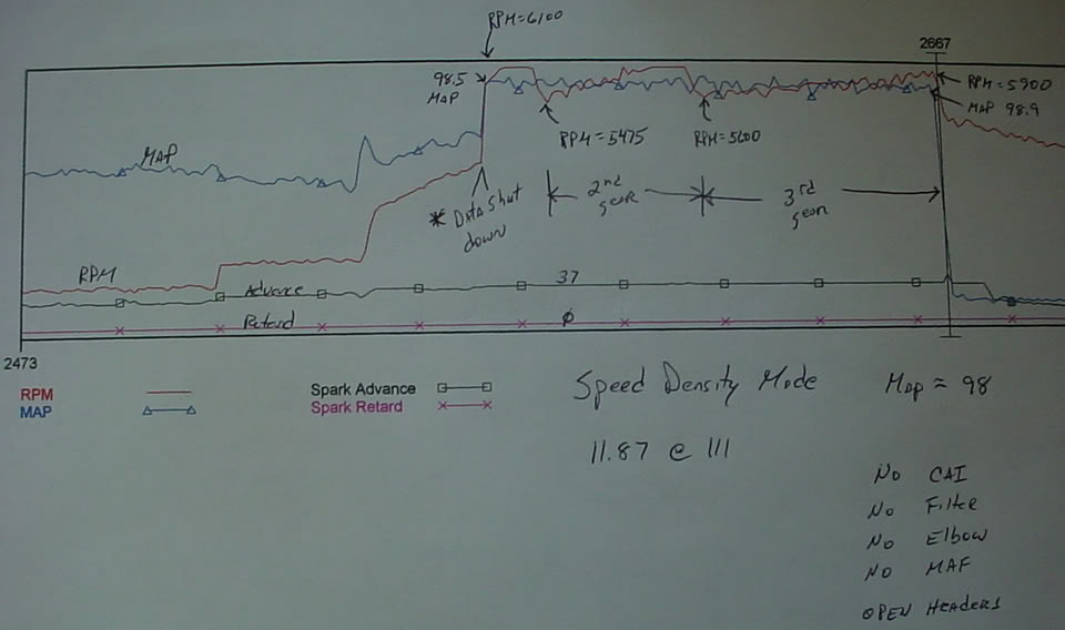
a) I've run it in Speed Density with all the intake parts off (elbow, MAF,CAI, filter) for a best of 11.87 @ 111 with no difference in 3rd gear (5500-5900)
b) I have long tube headers that exit straight out through electric cut-outs, so that eliminates the exhaust system.
Throttle body
Nitrous plate (bored out for 58mm TB)
intake manifold (ported and port matched to heads)
Heads
a) I've run it in Speed Density with all the intake parts off (elbow, MAF,CAI, filter) for a best of 11.87 @ 111 with no difference in 3rd gear (5500-5900)
b) I have long tube headers that exit straight out through electric cut-outs, so that eliminates the exhaust system.
Registered User
Joined: Oct 2007
Posts: 220
"I have long tube headers that exit straight out through electric cut-outs"
Actually that could be "a" problem. The cut outs need to be properly located in the exhaust system as part of the "collector length". Typically the best location for the cutout would be 18" beyond where the primary pipes end in the collector of the headers. Other lengths would be 36 and 72". In your case I bet something an inch or two shorter would be best.
Those dimensions may not be optimal for your car but they are in the ball park. If your cutouts are at say 27 inches or 54 inches that would be the worst locations and you could actually lose a few ponies. This is "wave" tuning.
Collector diameter is the next most important thing regarding the exhaust. I would suspect your best collector pipe diameter is somewhere 2 3/4" and 3". What size exhaust collector pipe do you have?
Last edited by 1989TransAm; Sep 4, 2008 at 11:14 PM.
Moderator
Joined: Dec 1969
Posts: 10,745
From: Buffalo, New York
I have enough experience to say, it depends. On an EFI car, the speed the ECU responds to changes in TPS voltage and the vacuum signal from the MAP sensor is the limiting factor. I have put a single plane manifold and a large TB on a '92 350 and there was just no way it could be tuned for throttle response. We must have burned 50 chips proving it and burned through a tank and a half of gas. Slapped the original TB back on and voila - it ran fine. OTOH, I am using a 2,200CFM TB on my race car (with an Electromotive TEC3r) and the throttle response is fine. LT1's seem to do fine with 58mm TB, I have not tried larger.
Rich
Rich

Registered User
Joined: Sep 1998
Posts: 458
From: Newark, DE.
Is that cam a solid roller cam? I sure hope so as that is a huge hydraulic cam for a 355 that could be taxing the lifters.
BTW, I will send you a couple lt1 edit files to try tonight. FWIW, my cam was a 235 242 .567 .592 (with 1.6's) 112lsa.
BTW, I will send you a couple lt1 edit files to try tonight. FWIW, my cam was a 235 242 .567 .592 (with 1.6's) 112lsa.
Thread Starter
Registered User
Joined: Sep 2004
Posts: 271
From: Canfield, OH
This is in speed density mode with all intake parts removed except TB:
MAP averages 98.5+
11.87 @ 111
laptop lost connection right after launch - you'll notice the missing data from 1st gear
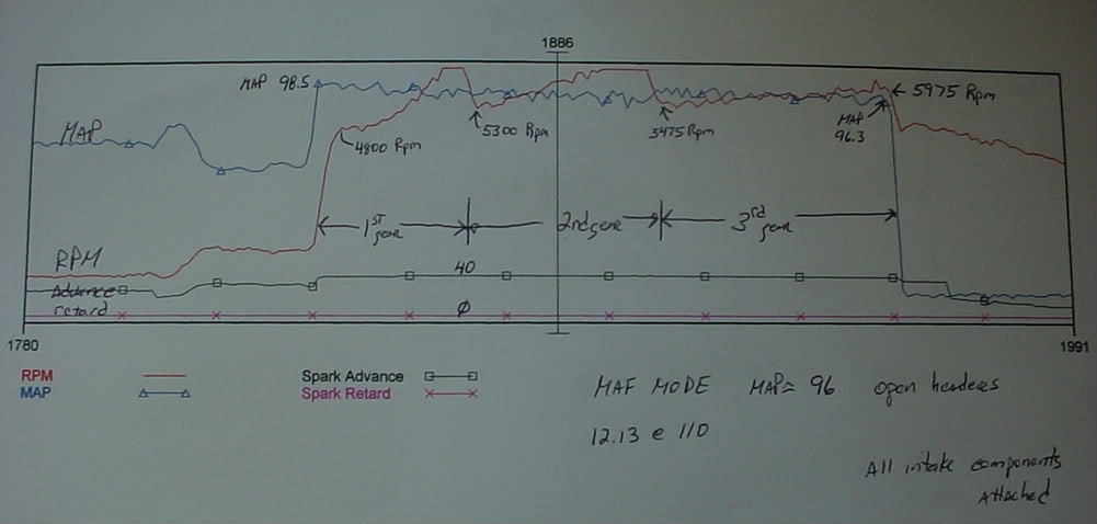
This is in MAF mode with all intake components attached (elbow, maf, cai, filter):
MAP averages about 97
12.13 @ 110
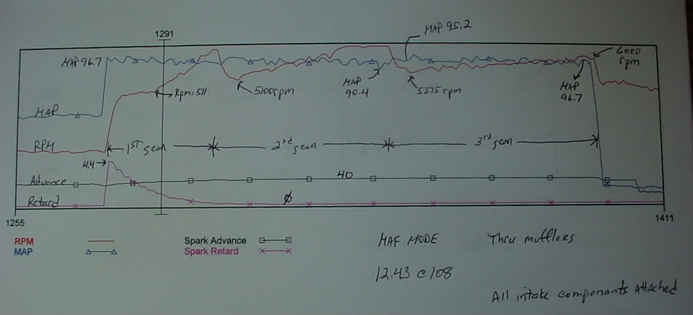
This one is in MAF mode witha all intake components and THRU MUFFLERS
MAP averages about 96
12.43 @ 108
It pulls timing thru the mufflers at launch - my guess is some added vibrations due to exhaust going thru entire system.
Thread Starter
Registered User
Joined: Sep 2004
Posts: 271
From: Canfield, OH
"I have long tube headers that exit straight out through electric cut-outs"
Actually that could be "a" problem. The cut outs need to be properly located in the exhaust system as part of the "collector length". Typically the best location for the cutout would be 18" beyond where the primary pipes end in the collector of the headers. Other lengths would be 36 and 72". In your case I bet something an inch or two shorter would be best.
Those dimensions may not be optimal for your car but they are in the ball park. If your cutouts are at say 27 inches or 54 inches that would be the worst locations and you could actually lose a few ponies. This is "wave" tuning.
Collector diameter is the next most important thing regarding the exhaust. I would suspect your best collector pipe diameter is somewhere 2 3/4" and 3". What size exhaust collector pipe do you have?
Actually that could be "a" problem. The cut outs need to be properly located in the exhaust system as part of the "collector length". Typically the best location for the cutout would be 18" beyond where the primary pipes end in the collector of the headers. Other lengths would be 36 and 72". In your case I bet something an inch or two shorter would be best.
Those dimensions may not be optimal for your car but they are in the ball park. If your cutouts are at say 27 inches or 54 inches that would be the worst locations and you could actually lose a few ponies. This is "wave" tuning.
Collector diameter is the next most important thing regarding the exhaust. I would suspect your best collector pipe diameter is somewhere 2 3/4" and 3". What size exhaust collector pipe do you have?
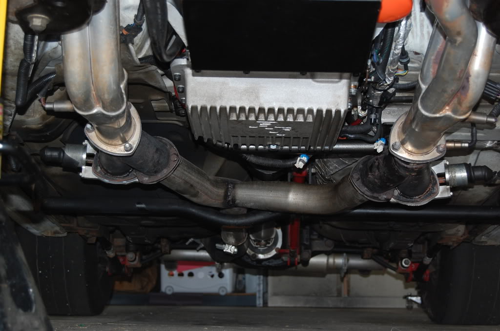
I have a set of Flowtech Race Readies (pictured) attached to the collectors and the cut-outs are on the straight end of the race readies.

They are 10 inches long - so add 10" to the collector length on the header (I can measure later when I get home) for the entire length of the system.
The "wyes" angle toward the center on both race readies (assume the race ready pictured is on the drivers side collector - looking from behind). Both "wyes" join together into one pipe that rides along the driveshaft and goes into a dual outlet Flowmaster system. I do not have cats.
I will get an exact collector length when I go home for lunch.
Thread Starter
Registered User
Joined: Sep 2004
Posts: 271
From: Canfield, OH
I have the stock lifters. I didn't want to mess with the Comp R's because I drive it to the track and around town on Saturdays.
I intended to buy a set from Cam Motion (I do not remember the name) when I got the cam, but I waited 3 months for them and I was told they were still 3 months out on back order, so I cancelled the order.
That's great for the LT1 edit files. I plan on going to the track tonight and getting the AFR down to 12.5 or so and start working up. I am very interested in the timing tables.
Thanks
Thread Starter
Registered User
Joined: Sep 2004
Posts: 271
From: Canfield, OH
"I have long tube headers that exit straight out through electric cut-outs"
Typically the best location for the cutout would be 18" beyond where the primary pipes end in the collector of the headers. Other lengths would be 36 and 72". In your case I bet something an inch or two shorter would be best.
Those dimensions may not be optimal for your car but they are in the ball park. If your cutouts are at say 27 inches or 54 inches that would be the worst locations and you could actually lose a few ponies. This is "wave" tuning.
18, 36, 72 = full waves (waves lengths appear to be doubling -yes?)
27 = half wave (1/2 way between 18 and 36)
54 = half wave (1/2 way between 36 and 72)
Very good information

Thread Starter
Registered User
Joined: Sep 2004
Posts: 271
From: Canfield, OH
I have 3" diamater collectors on Hooker Super Comp headers.
I have a set of Flowtech Race Readies (pictured) attached to the collectors and the cut-outs are on the straight end of the race readies.

They are 10 inches long - so add 10" to the collector length on the header (I can measure later when I get home) for the entire length of the system.
The "wyes" angle toward the center on both race readies (assume the race ready pictured is on the drivers side collector - looking from behind). Both "wyes" join together into one pipe that rides along the driveshaft and goes into a dual outlet Flowmaster system. I do not have cats.
I will get an exact collector length when I go home for lunch.
I have a set of Flowtech Race Readies (pictured) attached to the collectors and the cut-outs are on the straight end of the race readies.
They are 10 inches long - so add 10" to the collector length on the header (I can measure later when I get home) for the entire length of the system.
The "wyes" angle toward the center on both race readies (assume the race ready pictured is on the drivers side collector - looking from behind). Both "wyes" join together into one pipe that rides along the driveshaft and goes into a dual outlet Flowmaster system. I do not have cats.
I will get an exact collector length when I go home for lunch.
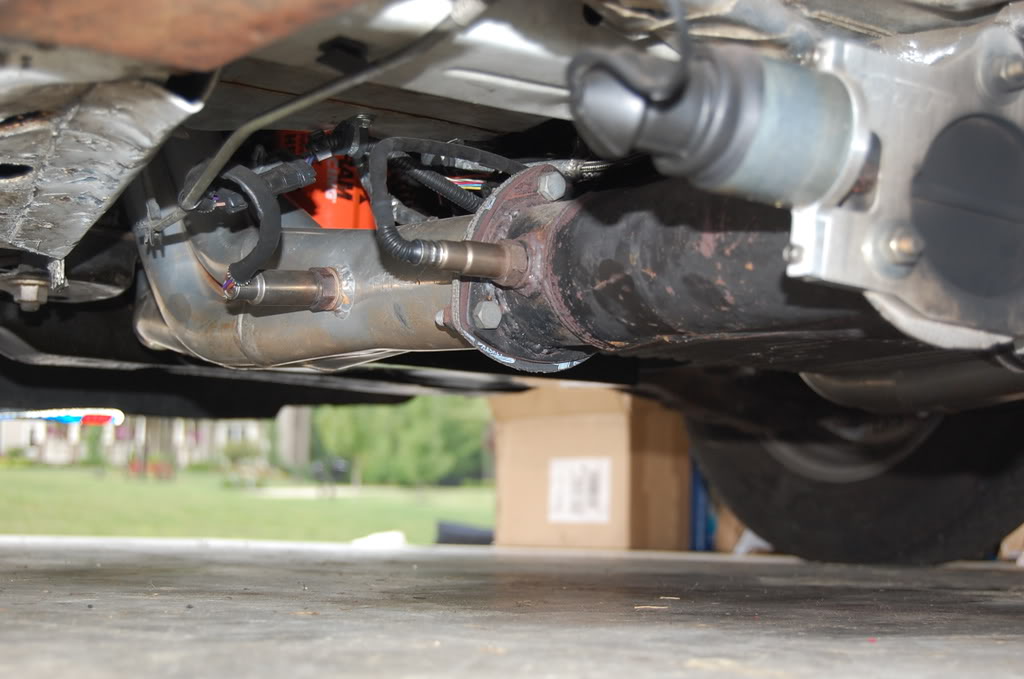
It seems hard to describe so I added a picture. Here's what it looks like from the front showing how the wyes turn to the inside and enter the single pipe to the muffler.