
Vacuum Line Diagram?


Thread Starter
Registered User
Joined: Jan 2006
Posts: 705
From: Waco, Texas
Vacuum Line Diagram?
The person I bought my car from totally didnt have the vacum lines hooked up to the manifold or anything so I need a diagram or something showing where they go etc also on the valve cover where that hole is doesnt a filter go there?? if so what is that part called I need to get a new one
Thread Starter
Registered User
Joined: Jan 2006
Posts: 705
From: Waco, Texas
Re: Vacuum Line Diagram?
hmm damn theres alot of lines missing, looking there I dont see the one for the one that goes to the fuel pump/gas tank.. the one thats suppose to vent for it or is that the evap can?
Last edited by Gun5; Apr 16, 2006 at 06:51 PM.
Administrator
Joined: Nov 1998
Posts: 71,122
From: Hell was full so they sent me to NJ
Re: Vacuum Line Diagram?
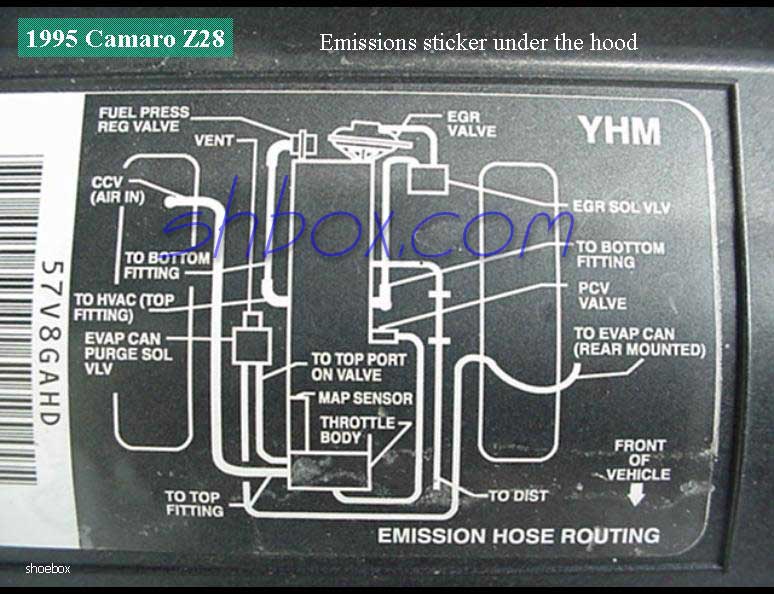
Yes.... that's the "3rd fuel line" in the bundle. Peels off the fuel line bundle middle of the drivers side of the intake manifold, connects to a U-shaped metal tube that runs forward under the TB.... turns to rubber somewhere under there, and the rubber hose runs to the EVAP purge solenoid on the metal bracket on the passenger side of the intake manifold.
The photo I linked is Shoebox's 95. Your 94 will be different, with the PCV valve vacuum coming from a U-shaped hose back into the drivers side of the intake manifold, and not like the 95 running to a port under the throttle body.
The diagram also does not show the vacuum line from the second port on the passenger side of the intake manifold for the vacuum supply to the heat/AC controls check valve.
Last edited by Injuneer; Apr 17, 2006 at 12:14 AM.
Thread Starter
Registered User
Joined: Jan 2006
Posts: 705
From: Waco, Texas
Re: Vacuum Line Diagram?
im assuming when I get my new valve cover breather it needs a PCV line??
also what size is the hole on the stock because K & N has a few different sizes to choose from fori t
also what size is the hole on the stock because K & N has a few different sizes to choose from fori t
Last edited by Gun5; Apr 18, 2006 at 01:28 AM.
Administrator
Joined: Nov 1998
Posts: 71,122
From: Hell was full so they sent me to NJ
Re: Vacuum Line Diagram?
If you put a "breather" on the valve cover, you need to block off the vacuum nipple for the vent line on the throttle body. That's it. The PCV valve is on the driver's side of the intake, and will pull the air in through the breather. Its technically a minor vacuum leak, because with the vent line in place, the air that got pulled through the vent line and the PCV valve had been measured by the MAF sensor. What enters through the "breather" won't be.

Thread
Thread Starter
Forum
Replies
Last Post

