
Fan Switch Mod


Thread Starter
Registered User
Joined: Dec 2010
Posts: 56
Fan Switch Mod
Im just trying to find out if someone out there has pics or is willing to be patient with me, ive never done anything electrical, just trying to learn, plus i wanna make sure before i screw some thing up
3 resistors
http://www.radioshack.com/product/in...ductId=2062313
Toggle switch
http://www.radioshack.com/product/in...ductId=2062506
and does the wire matter?
Am i able to just splice in since i dont know how to solder, i read in some past searches about wire taps? Would this be an option?
Last i dont quite understand the led lingo based off of shoeboxs diagram, i barely understand some of it
Thanks for your patience
Last edited by GMC5.3; Feb 4, 2012 at 10:57 PM. Reason: didnt work
Registered User
Joined: Dec 1969
Posts: 27,728
From: Little Rock, AR
Re: Fan Switch Mod
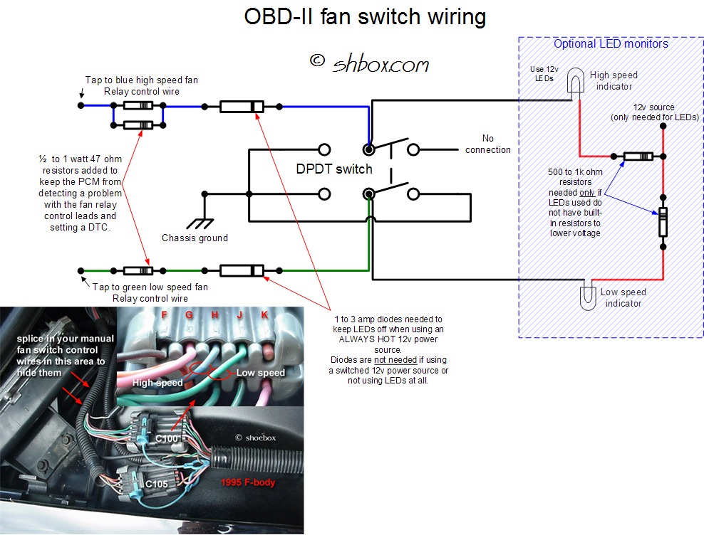
You cannot use that switch. It is a SPST-not a DPDT. It does not have enough lugs on the back. The resistors are ok. I would not do anything other than solder and heatshrink wrap for the resistors. You can probably find video instructions somewhere on the internet. It's not hard. You could probably get by with wire taps to connect to the blue and green wires in the car's harness. Wire gauge should be no smaller than the stock gauge (about 22 gauge).
If you want to do the LEDs the simplest way, get 12v LEDs and use a switched power source to avoid having to use diodes. If you use a non switched power source for the LEDs and no diodes, the lights won't act right. If you don't use the resistors at the left hand side of the diagram, you will get trouble codes when you turn the switch on (OBD-II only).
If you want to do the LEDs the simplest way, get 12v LEDs and use a switched power source to avoid having to use diodes. If you use a non switched power source for the LEDs and no diodes, the lights won't act right. If you don't use the resistors at the left hand side of the diagram, you will get trouble codes when you turn the switch on (OBD-II only).
Registered User
Joined: Sep 2001
Posts: 4,152
From: Woodstown, NJ
Thread Starter
Registered User
Joined: Dec 2010
Posts: 56
Re: Fan Switch Mod
Should the resistors be covered with heat shrink tubes, and on the diagram the bottom left terminal is a wire going to a ground correct? So im just using the 2 middle terminals and the bottom left to a ground?
Registered User
Joined: Dec 1969
Posts: 27,728
From: Little Rock, AR
Re: Fan Switch Mod
The wire legs of the resistors should be insulated. Heat shrink would be good. There are three terminals of the switch that should be joined to ground. I can't teach you how to read a schematic, but it is all right there.
Thread Starter
Registered User
Joined: Dec 2010
Posts: 56
Re: Fan Switch Mod
I beleive i got it, the first 2 on the left and the bottom right, connecting to 1 wire that states (chassis ground)
Registered User
Joined: Oct 2007
Posts: 1,174
Re: Fan Switch Mod

Registered User
Joined: Dec 1969
Posts: 27,728
From: Little Rock, AR

Administrator
Joined: Nov 1998
Posts: 71,110
From: Hell was full so they sent me to NJ
Registered User
Joined: Aug 2011
Posts: 78
From: Lexington, KY
Re: Fan Switch Mod
I've ran mine full time for a couple years and have had no problem with them. I do plan to wire them back up to run like factory, but I have to figure out why they werent coming on.
Registered User
Joined: Dec 1969
Posts: 27,728
From: Little Rock, AR
Re: Fan Switch Mod
Registered User
Joined: Oct 2007
Posts: 1,174
Re: Fan Switch Mod
