
4 PCM codes. Please help! Thanks


Thread Starter
Registered User
Joined: Jan 2006
Posts: 1,127
From: Dallas, TX
4 PCM codes. Please help! Thanks
Alright, got 4 codes in my pcm. Following codes: 96 Z28
1351 (think it was random misfire) But this is major!
1441 (Auxilary Emissions for MAP sensor I think)
1641 (same as 1441 I think)
1642 (" ")
Well. Got a new opti, new MAP sensor, new ignition control module, new MSD coil, new wireset, new fuel pump, fuel pressure regulator and a fuel pressure guage. Dont know what is causing this mis unless the damn opti went out that fast. I got some new injectors but tuning so I can run them but cant tune til I fix the misfire. Also new NGKTR55IX plugs, gapped @ 35. Got all that stuff on here and its really bad in first gear and @ 60-100mph. cant get it over 110 mph. If anyone knows what these codes are and what to look for or how to fix this prob, please help. Thanks for any input!

Guest
Joined: Sep 2004
Posts: 0
Sounds like you have some bad wiring.
The 1351 is the Ignition Control(IC) circuit from the PCM to the ICM. It commands the ICM to fire the coil. In the case of a 1351, this wire is above 4.6 volts when it should be at 0 volts. The IC line is the white wire that runs from the black PCM connector pin 5 to the ICM.
The DTC 1441 is an EVAP system flow during NON_PURGE code. There is a vacuum switch between the engine intake manifold and the evap purge solenoid. When the solenoid is commanded open, the switch opens to let the PCM know the vacuum is flowing. In your case, the solenoid is not commanded open but the switch is still open when it should be closed.
The DTC 1641 is for one of the cooling fan relays and the 1642 is for the other 2 fan relays.
Guest
Joined: Sep 2004
Posts: 0
The fans are turned on and off by the PCM. It will provide a ground to the relay when it wants a fan to turn on. This completes the circuit to the relay coil causing the relay to pull in and thus turns on the fan. There is always 12 volts going to the relay coil but it only gets ground (completing the circuit) when the PCM wants the fan on.
In the case of the 1641 or the 1642, the PCM has detected a voltage other than battery voltage on the wire that turns on the relay. It signals by throwing a code.
To explain further, many of the control signals from the PCM are also monitored to be sure they are at the correct potential at times they are not being used. So in the case of the relay control lines, the control line from the PCM to the fan control relays should hover near battery voltage until the PCM pulls it to ground completing the circuit to the relay and thus turning on the relay. Until it pulls the control line to ground, it monitors the line to see if it is at battery voltage.
What you are concerned with here are the dark blue and dark green wires going to the red PCM connector on pins 10 and 11. There should be 12 volts there all the time. If there is no power there, check the 25amp fuse #7 under hood. If it's low voltage but not zero, start by checking the voltage at the battery.
Incidentally, there is one common item that might explain all your symptoms. If the 12 volts supplied by the battery and the alternator were either lower than threshold OR it had too much AC voltage on it. It could cause random PCM failures of varying types. THEREFORE it is a good idea to eliminate the charging system as the cause of weird electrical failures BEFORE going on a wild goose chase.
To do that is simple. Start the vehicle and measure the DC voltage across the battery terminals. It should be around 14 volts. Now to check AC leakage from the alternator, set the meter to AC and measure from the negative battery terminal to the large output post of the alternator. It should NOT be above 0.03 volts AC. If it is above that, the diodes inside the alternator are defective and they are allowing too much AC voltage to get on the 12 volt line. Too much AC can, (notice I said can) make the PCM do strange things.
Good luck
Last edited by Guest47904; Apr 15, 2007 at 07:19 AM.
Registered User
Joined: Dec 1969
Posts: 27,728
From: Little Rock, AR
If you have a fan switch and it is not wired in a particular manner, you will get the fan relay control trouble codes. The "DTCs" link in my sig goes to a listing of f-body specific trouble codes (so you can reference any future codes). There are also fan switch wiring diagrams in the schematics section of my Tech Page.
BTW, I am wondering why you list a 180� thermostat in your mods. That's the stock thermostat.
BTW, I am wondering why you list a 180� thermostat in your mods. That's the stock thermostat.
Guest
Joined: Sep 2004
Posts: 0
Thread Starter
Registered User
Joined: Jan 2006
Posts: 1,127
From: Dallas, TX
P1351 Ignition Control (IC) circuit high voltage (open circuit)
P1441 Evaporative Emissions (EVAP) system flow during non-purge
P1641 Fan Control (FC) relay 1 control circuit
P1642 Fan Control (FC) relay 2 and 3 control circuit
P1441 Evaporative Emissions (EVAP) system flow during non-purge
P1641 Fan Control (FC) relay 1 control circuit
P1642 Fan Control (FC) relay 2 and 3 control circuit
Thread Starter
Registered User
Joined: Jan 2006
Posts: 1,127
From: Dallas, TX
The 1351 is the Ignition Control(IC) circuit from the PCM to the ICM. It commands the ICM to fire the coil. In the case of a 1351, this wire is above 4.6 volts when it should be at 0 volts. The IC line is the white wire that runs from the black PCM connector pin 5 to the ICM.
The DTC 1441 is an EVAP system flow during NON_PURGE code. There is a vacuum switch between the engine intake manifold and the evap purge solenoid. When the solenoid is commanded open, the switch opens to let the PCM know the vacuum is flowing. In your case, the solenoid is not commanded open but the switch is still open when it should be closed.
So whats the best way to go about fixing these?
Thread Starter
Registered User
Joined: Jan 2006
Posts: 1,127
From: Dallas, TX
The DTC 1441 is an EVAP system flow during NON_PURGE code. There is a vacuum switch between the engine intake manifold and the evap purge solenoid. When the solenoid is commanded open, the switch opens to let the PCM know the vacuum is flowing. In your case, the solenoid is not commanded open but the switch is still open when it should be closed.
Registered User
Joined: Dec 1969
Posts: 27,728
From: Little Rock, AR

Thread Starter
Registered User
Joined: Jan 2006
Posts: 1,127
From: Dallas, TX
Well which sensors are the EVAP solenoid and the vacuum switch. Would these affect performance? I took out the EGR and the one sensor in the back driverside that hooks to it is still there, is that one of them? I know theres 2 sensors on the pass side, one has red connector and the other has grey connector. The red one has vacuum to the grey one and to the throttle body. I am mainly concerned with the 1351, thats whats causing my misfire.
Thread Starter
Registered User
Joined: Jan 2006
Posts: 1,127
From: Dallas, TX
I just loked at a schematic of the vacuum layout and it says that the sensor your saying that should be closed/open is connected to the charcoal canister @ some point. I changed the fuel pump recently and I am almost certain I left a vacuum line unhooked which will cause this DTC.
Thread Starter
Registered User
Joined: Jan 2006
Posts: 1,127
From: Dallas, TX
I think I fixed the 1351 code, I have no misfire in first gear rpms and/or 60-100mph and I can go over 100. I think the 1441 is the canister because a technician hooked it up to a Snap-On scanner and thats what it said. The fans, not sure, they might be cleared.
Also wanted to ask you, what should I gap my plugs @? N/A 450-500hp ish. I have the NGKTR55IX which is the iridium. The manual says 35 but I think its suppose to be 50. But I gapped them all @ 35, think I should go back and change them to 50?
Also wanted to ask you, what should I gap my plugs @? N/A 450-500hp ish. I have the NGKTR55IX which is the iridium. The manual says 35 but I think its suppose to be 50. But I gapped them all @ 35, think I should go back and change them to 50?
Administrator
Joined: Nov 1998
Posts: 71,110
From: Hell was full so they sent me to NJ
Shoebox has the diagram of the engine compartment located components for the EVAP system. The vacuum switch is not in the line from the solenoid to the throttle body. Its in the line from the canister to the solenoid. See component #11:
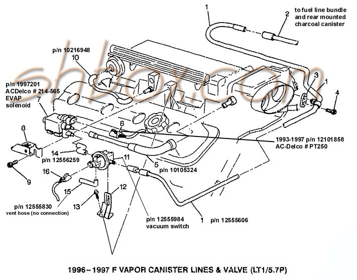
The most common problem is an EVAP purge solenoid being held open by accumulated carbon particles. Take the solenoid off the bracket on the side of the manifold and open it up with +12V and a ground. Blow air through it to clear the passage of any particles.
You will also get the code if you have the lines on the solenoid switched.