
2 Questions: Finding TDC without removing front cover & ring orientation


Thread Starter
Registered User
Joined: Aug 2000
Posts: 359
From: Victorville, CA
2 Questions: Finding TDC without removing front cover & ring orientation
I'll make it short and sweet. My engine was sitting for almost 6 years after my original powertrain was stolen by the shop I where was doing my Vega's LT1/T56 conversion. I finally have the motivation to work on the car and I noticed the engine had a lot of crap near the exhaust ports on the heads. I yanked the heads and found a ton of dirt in two cylinders. I have honed those two cylinders after removing the pistons but here's my quandry. My oil/compression rings are way different than shbox.com's.
He suggests:
I have:

Am I screwed? Or will I be ok? Now's the time to fix it if I absolutely have to have the orientation on shbox.com.
Lastly, the shop that rebuilt my LT1 damaged my crank snout and pulled about 1/4-1/3 of the threads out of the crank snout. I don't want to yank the balancer hub to see if I'm at TDC or 180 out but I need to set the lifters. What's the best way to do that? I have the oilpan off the engine. Maybe look at where the lobes are at? Or just set the lifters and if it backfires out the intake turn the crank one revolution and set them again?
Any help is appreciated.
Thanks,
Colin
He suggests:
I have:
Am I screwed? Or will I be ok? Now's the time to fix it if I absolutely have to have the orientation on shbox.com.
Lastly, the shop that rebuilt my LT1 damaged my crank snout and pulled about 1/4-1/3 of the threads out of the crank snout. I don't want to yank the balancer hub to see if I'm at TDC or 180 out but I need to set the lifters. What's the best way to do that? I have the oilpan off the engine. Maybe look at where the lobes are at? Or just set the lifters and if it backfires out the intake turn the crank one revolution and set them again?
Any help is appreciated.
Thanks,
Colin

Registered User
Joined: Jul 2003
Posts: 553
From: Southern California
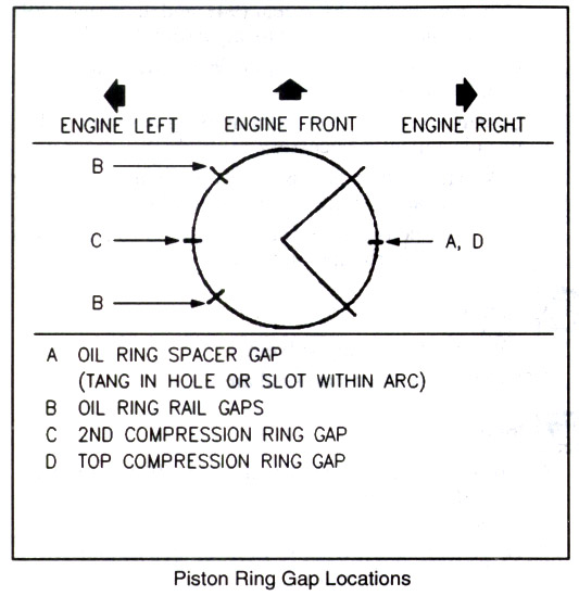
The primary consideration in staggering the ring gaps is to make sure that they aren't all in the same vertical plane. If both of the pistons you have removed are staggered in the manner you show in the diagram, you should be good to go. Apparently, the assembler of that short block subscribes to a different alignment scheme but just make sure that the two compression ring gaps are 180 degrees from one another. Split the difference between the rail gaps to make sure that they are opposite the expander gap and roughly 90 degrees apart.
Finding TDC is another challenge altogether. General Motors did us no favors by neglecting to include a timing indicator on the LT motor. If you have the pan and intake off the motor you should be able to get a rough determination of where you are but you won't have a precise TDC mark unless you use a degree wheel and a piston stop.
If the heads are off the block and you have a relatively stock camshft, you can rotate the crank until the #1 piston is at the top of the stroke. To determine if the cam is up on #1 or #6, put all the lifters in the block on the driver's side. Using a straight edge, compare the elevation of the lifters. The following lifters should be sitting on the base circle of the camshaft and their tops will be on a level horizontal plane when measured with a straight edge: #1 I, #1E, #3E, #5I, #7I. If they are not even (that is, one or more of them is much higher than the others) the cam is on the #6 compression stroke. Once you know where you are, you can install the heads and proceed with your normal valve adjustment procedure.
I suggest that you do something to mark the dampener so that you know where TDC is located. I have fabricated a positive pointer that is bolted to the motor and works in conjunction with a dampener that is engraved at one degree intervals around the circumference. At the very least, I would mark the dampener at TDC and at 90 degree intervals. The pointer should be permanently mounted in a manner that it doesn't vibrate excessively when the motor is running.
I hope these suggestions are clear enough to follow. I'm shaking off the effects of a dose of Nyquil this morning. If this is unclear, ask again. You'll get through this stage of frustration and on to something else quickly enough.
Good luck,
c
Registered User
Joined: Aug 2005
Posts: 4,405
From: Kantuckee Yo'
Get a brass dead stop and screw it any spark plug hole. Attach a degree wheel to the balancer with double sided tape, make a pointer and you quickly get TDC. Turn the motor both ways till it stops get the two markings off the wheel. Split the difference and you have TDC.

Registered User
Joined: Jan 2006
Posts: 325
From: Back in the US of F'in A
I use a piston stop IOT find TDC when the heads are on or my dial indicator and a bridge when the heads are off.
However, I don't look for TDC when I adjust my my valves.
I just use EO IC IMHO It is easier than trying to find tdc (on my LT1 vette)
do a quick google and you'll be good to go
As for ring gaps as others have posted main thing is to keep the ring gaps staggered.
Good luck
Mike
However, I don't look for TDC when I adjust my my valves.
I just use EO IC IMHO It is easier than trying to find tdc (on my LT1 vette)
do a quick google and you'll be good to go
As for ring gaps as others have posted main thing is to keep the ring gaps staggered.
Good luck
Mike
Thread Starter
Registered User
Joined: Aug 2000
Posts: 359
From: Victorville, CA
thanks for the help, guys 
I got the engine back together this evening. Everything else came out fine. I did check the engine builder's work with Plastigage and all main and rod bearings are well within spec.
I'm excited to get this car running even though it's going to initially be carbureted. Even still, I bet it'll be quite quick even with a stock LT1/T56 powertrain backed by 12-bolt 3.73 in a 2500lb car. I hope it has serious traction problems even with the IROC-Z wheels.
Thanks again,
Colin
I got the engine back together this evening. Everything else came out fine. I did check the engine builder's work with Plastigage and all main and rod bearings are well within spec.
I'm excited to get this car running even though it's going to initially be carbureted. Even still, I bet it'll be quite quick even with a stock LT1/T56 powertrain backed by 12-bolt 3.73 in a 2500lb car.
I hope it has serious traction problems even with the IROC-Z wheels.Thanks again,
Colin
Registered User
Joined: Oct 1998
Posts: 3,144
From: Jackstandican
I believe you have to adjust a piston stop to find TDC. It's not like you can pull it out of a box and voila- TDC. So basically (if I'm not mistaken) you must find TDC first, then adjust the piston stop to do the other cylinders. A very crude way to do it, yet very effective is to get a McDonald's straw (or some other large diameter straw), feed it into the spark plug hole, rotate engine, tug on straw and naturally when you reach the most resistance you've achieved TDC. You must make sure the straw is in far enough to be between the piston and quench area.

Thread
Thread Starter
Forum
Replies
Last Post
dbusch22
Forced Induction
6
Oct 31, 2016 11:09 AM
PFYC
Supporting Vendor Group Purchases and Sales
0
Dec 4, 2014 11:56 AM
1LEThumper
Forced Induction
40
Jul 14, 2003 12:45 PM