MikeGyver's Turbo 383 Build.
 09-01-2010, 12:58 AM
#31
Registered User
Thread Starter
Join Date: Aug 2006
Location: Orem, UT
Posts: 1,497
Worked on the car a bit more tonight.
On a 3.5" tube @ 15psi, there will be about 95 pounds of force trying to pop the pipe out of the silicone, so I decided to bead roll the ends of the intake tube.
I was able to use a bead roller from shipwreck tools... after bracing it.
Since there's no way i could have precisely rotated this big pipe around a dozen times, I cut the ends off of it at the existing welds, and re-welded on the straight pieces that I had bead rolled.
I think the fabrication of this pipe is now done.


I also put together a cat delete pipe. The cat is held in with a V-band clamp on each end, so I can swap in the pipe in minutes.


On a 3.5" tube @ 15psi, there will be about 95 pounds of force trying to pop the pipe out of the silicone, so I decided to bead roll the ends of the intake tube.
I was able to use a bead roller from shipwreck tools... after bracing it.
Since there's no way i could have precisely rotated this big pipe around a dozen times, I cut the ends off of it at the existing welds, and re-welded on the straight pieces that I had bead rolled.
I think the fabrication of this pipe is now done.
I also put together a cat delete pipe. The cat is held in with a V-band clamp on each end, so I can swap in the pipe in minutes.
 09-01-2010, 08:05 AM
#32
Registered User
Join Date: Dec 1999
Location: Upstate New York,USA
Posts: 1,791
Great idea on the bead roller. I can't tell you how many times I was seen on the side of the road during my lunch hour, using my dash saver screen as my creeper, cussing and pushing my pipes back into the couplers after they popped off. I stopped into a shop in Houston lamented the numerous pop offs to the shop owner. He said, "let me bead roll the pipe ends for you". I said "what's a bead roller?". Lol... He removed all the plain cut ends, bead rolled them and reinstalled. All for free. Great guy. I made sure I went back to his shop and purchased some things. Ever since then? No pop offs.
I didn't know Harbor Freight sold bead rollers! Do you have the part number? I'll see if I can look it up on their site.
Once again, your weld quality is just "Art". Certainly among the best I've ever seen.
I didn't know Harbor Freight sold bead rollers! Do you have the part number? I'll see if I can look it up on their site.
Once again, your weld quality is just "Art". Certainly among the best I've ever seen.
 09-01-2010, 05:04 PM
#34
Registered User

Join Date: May 2009
Posts: 3
Worked on the car a bit more tonight.
On a 3.5" tube @ 15psi, there will be about 95 pounds of force trying to pop the pipe out of the silicone, so I decided to bead roll the ends of the intake tube.
I was able to use a bead roller from shipwreck tools... after bracing it.
Since there's no way i could have precisely rotated this big pipe around a dozen times, I cut the ends off of it at the existing welds, and re-welded on the straight pieces that I had bead rolled.
I think the fabrication of this pipe is now done.
I also put together a cat delete pipe. The cat is held in with a V-band clamp on each end, so I can swap in the pipe in minutes.

Ha Ha What's up Mikey.........
09-01-2010, 11:21 PM
#35
Registered User
Thread Starter
Join Date: Aug 2006
Location: Orem, UT
Posts: 1,497
lol...
So I was bored today and made the mounting bracket for my MSD 6A. I wanna get some 3M VHB double sided tape to permanently secure the MSD to the bracket.
I also polished the intake elbow that was powdercoated black. The pipes will be ceramic coated and polished silver so the black was out of place, especially since I'm not using my powdercoated black intake.


Polished

So I was bored today and made the mounting bracket for my MSD 6A. I wanna get some 3M VHB double sided tape to permanently secure the MSD to the bracket.
I also polished the intake elbow that was powdercoated black. The pipes will be ceramic coated and polished silver so the black was out of place, especially since I'm not using my powdercoated black intake.
Polished
Last edited by MikeGyver; 09-02-2010 at 06:07 AM.
09-10-2010, 06:18 AM
#37
Registered User
Thread Starter
Join Date: Aug 2006
Location: Orem, UT
Posts: 1,497
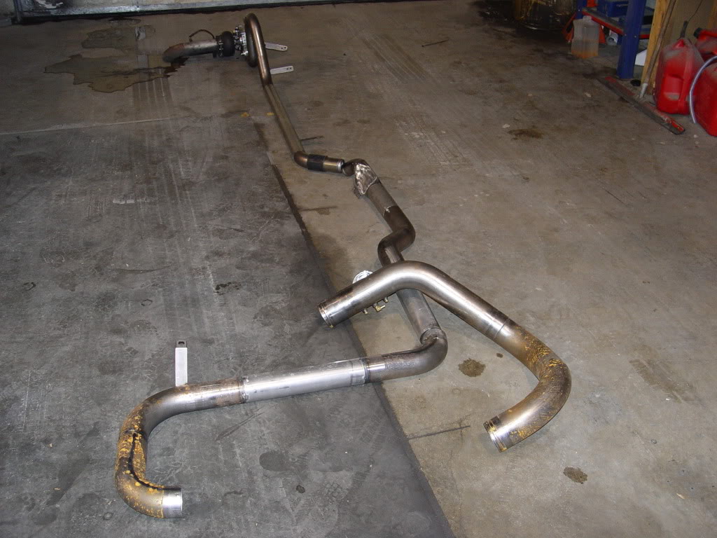
I started on the pre-intercooling piping a couple days ago.
Here are the two new 3" pipes compared to the two old 2.25" ones. The intercooler inlet is at the end on the bottom right of the picture. Further back where the pipe shoots straight back is where it goes between the engine and the frame on the driver side.

Here are the two new 3" pipes compared to the two old 2.25" ones. The intercooler inlet is at the end on the bottom right of the picture. Further back where the pipe shoots straight back is where it goes between the engine and the frame on the driver side.

 09-18-2010, 04:49 PM
#39
Registered User
Thread Starter
Join Date: Aug 2006
Location: Orem, UT
Posts: 1,497
Last night was the last street legal drags of the season at Rocky Mountain Raceways, so I decided to throw the (incomplete) turbo system together and run it on 7psi.
I had my 60# mototrons cleaned, and borrowed a Turbonetics T66 which can support up to 720 flywheel HP, and threw the system together.
All the ricers showed up in their 17 second 10-second cars, so waiting in line for 3 1/2 hours netted me two runs down the track. Anyway It ran a 12.64 @ 115.96mph on a 2.2 second 60 ft. RMR's elevation is about 4300' so we're about 3/4 of a second slower up here than at sea level.
Since I'm running a 1bar speed density tune, the last row of cells has to dump in enough fuel (and appropriate timing) for the max 7psi (135kpa), so until it gets there, there's a deadzone where the timing is low and its super rich, as you can see in the VE table (fueling).

Should easily be in the 11's when I finish it up and it's running 12-15psi on a 76mm turbo with a 2bar tune

I had my 60# mototrons cleaned, and borrowed a Turbonetics T66 which can support up to 720 flywheel HP, and threw the system together.
All the ricers showed up in their 17 second 10-second cars, so waiting in line for 3 1/2 hours netted me two runs down the track. Anyway It ran a 12.64 @ 115.96mph on a 2.2 second 60 ft. RMR's elevation is about 4300' so we're about 3/4 of a second slower up here than at sea level.
Since I'm running a 1bar speed density tune, the last row of cells has to dump in enough fuel (and appropriate timing) for the max 7psi (135kpa), so until it gets there, there's a deadzone where the timing is low and its super rich, as you can see in the VE table (fueling).
Should easily be in the 11's when I finish it up and it's running 12-15psi on a 76mm turbo with a 2bar tune
Last edited by MikeGyver; 09-18-2010 at 05:14 PM.
11-06-2010, 06:57 AM
#41
Registered User
Thread Starter
Join Date: Aug 2006
Location: Orem, UT
Posts: 1,497
Re: MikeGyver's Turbo 383 Build.
Well I had an oppritunity to dyno so I jumped on it.
put down 528rwhp and 531tq on the BB turblonetics T66 at 9psi
I was having a hell of a hard time trying to tune it and I found out why, my walbro is completely maxing out. The abrupt loss of power at 4500rpm+ is when the fuel pressure dropped from ~53psi to 30. I was unknowingly compensating for this with a very rich tune.
Anyway I'm going to put another walbro in and try again with a 76mm BB turbo. Looks like it could be over 550rwhp if it doesn't lean out.


Here's the dyno video: http://www.youtube.com/watch?v=Sbf41sp8efM
And a little HD burnout video : http://www.youtube.com/watch?v=8hvxUaadk1M
put down 528rwhp and 531tq on the BB turblonetics T66 at 9psi
I was having a hell of a hard time trying to tune it and I found out why, my walbro is completely maxing out. The abrupt loss of power at 4500rpm+ is when the fuel pressure dropped from ~53psi to 30. I was unknowingly compensating for this with a very rich tune.
Anyway I'm going to put another walbro in and try again with a 76mm BB turbo. Looks like it could be over 550rwhp if it doesn't lean out.
Here's the dyno video: http://www.youtube.com/watch?v=Sbf41sp8efM
And a little HD burnout video
: http://www.youtube.com/watch?v=8hvxUaadk1M
Last edited by MikeGyver; 11-27-2010 at 10:38 PM.

 11-17-2010, 10:27 PM
#44
Registered User
Thread Starter
Join Date: Aug 2006
Location: Orem, UT
Posts: 1,497
Re: MikeGyver's Turbo 383 Build.
Finished up all my new intake piping a couple days ago. Should be back from ceramic coating in a week or so.
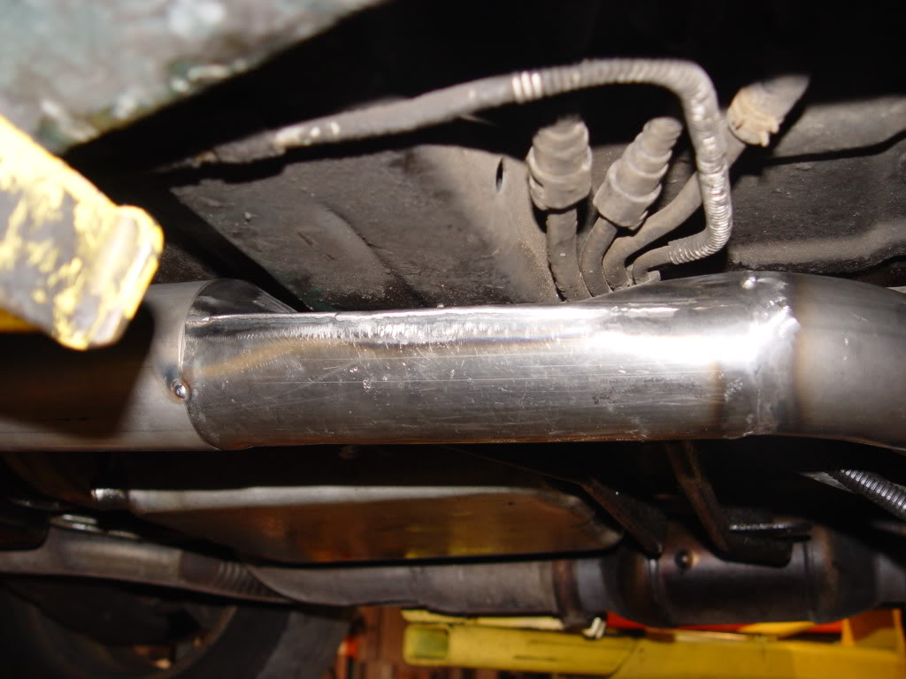
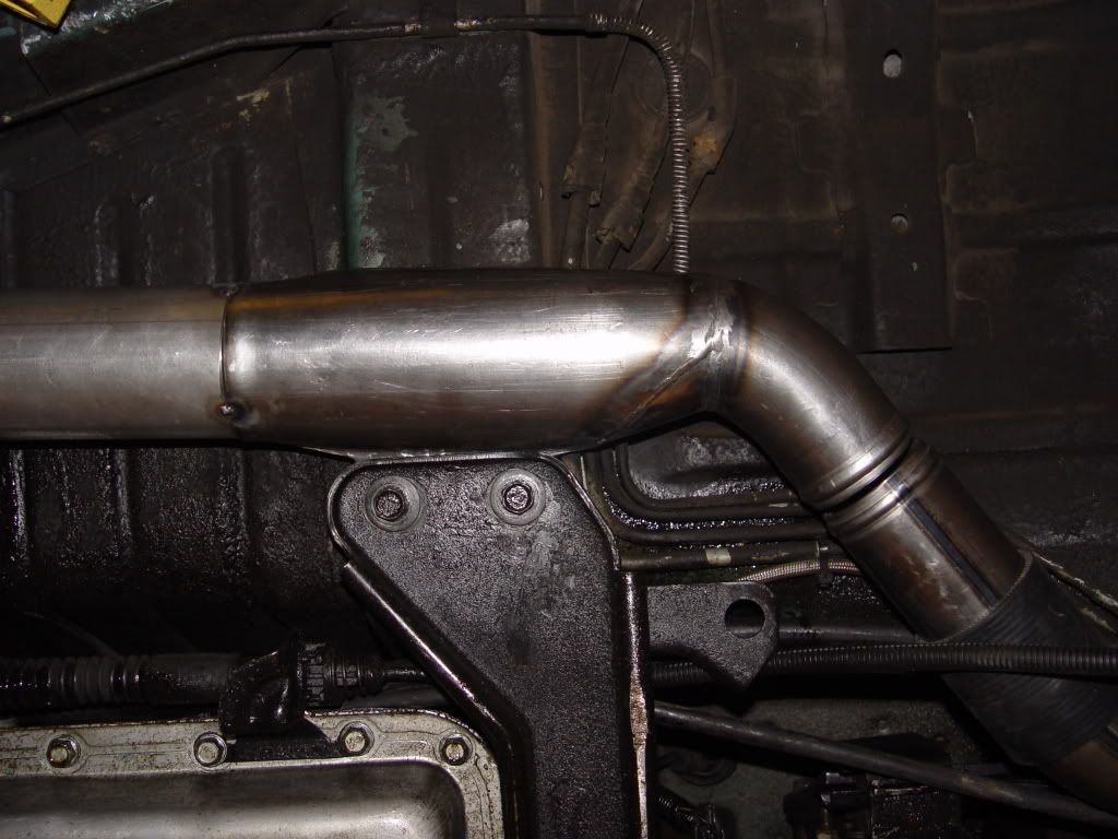
Piping is 2.5" out of the 76mm turbo till the high-clearance transition pipe, then it's 3" to the intercooler, and 3.5" from intercooler to engine.
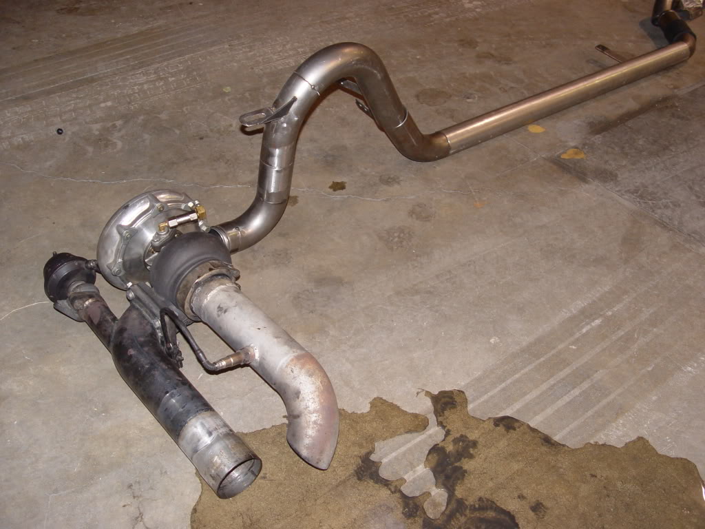
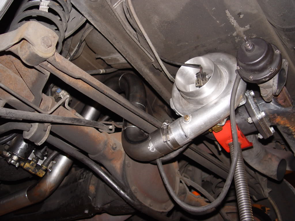
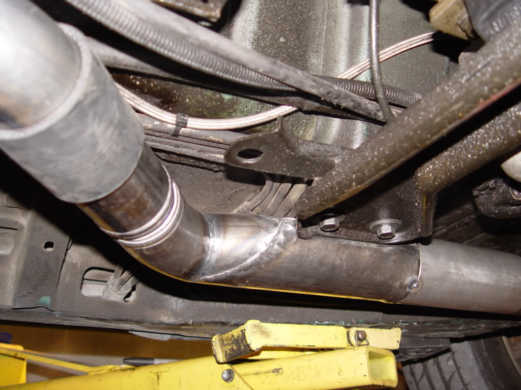
Here's the 2.5" to 3" transition pipe. It's the lowest point and has to get past a convertible brace. It's 3.5" pipe cut in half and capped (1.75" tall), so it's cross sectional area is about the same as the 2.5" tubing feeding into it.
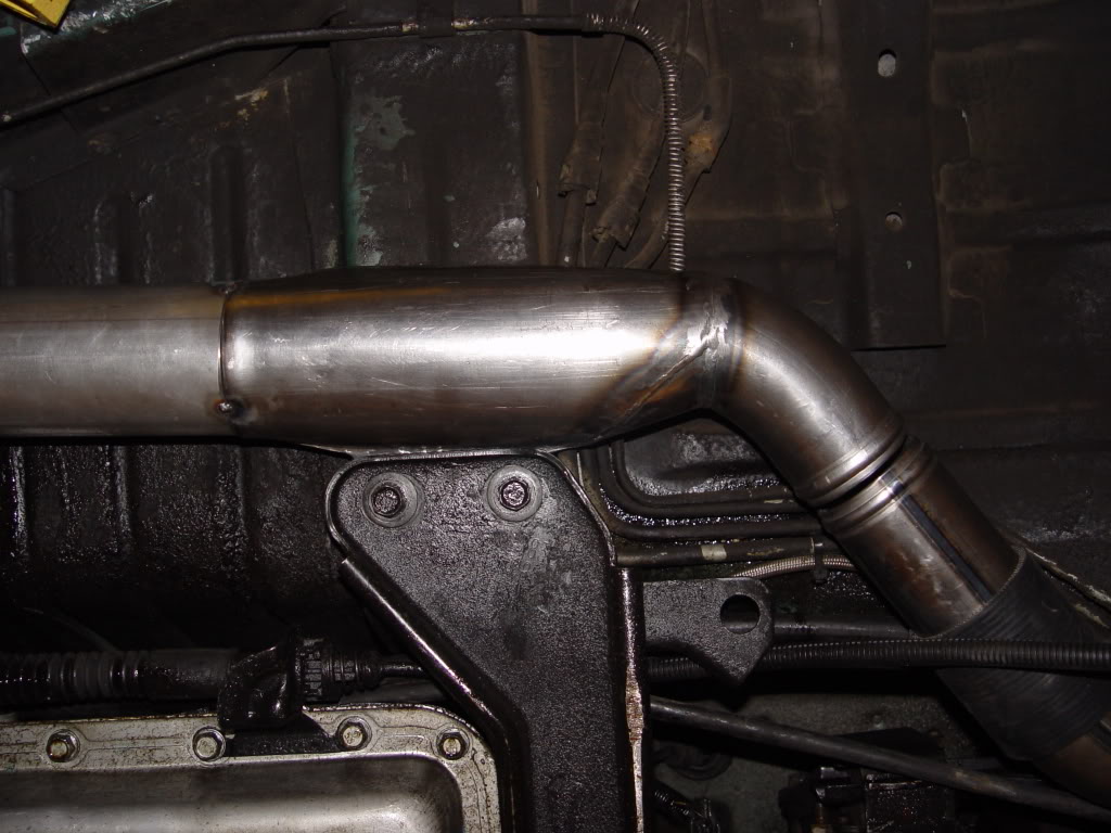
Another view showing clearance restraints.
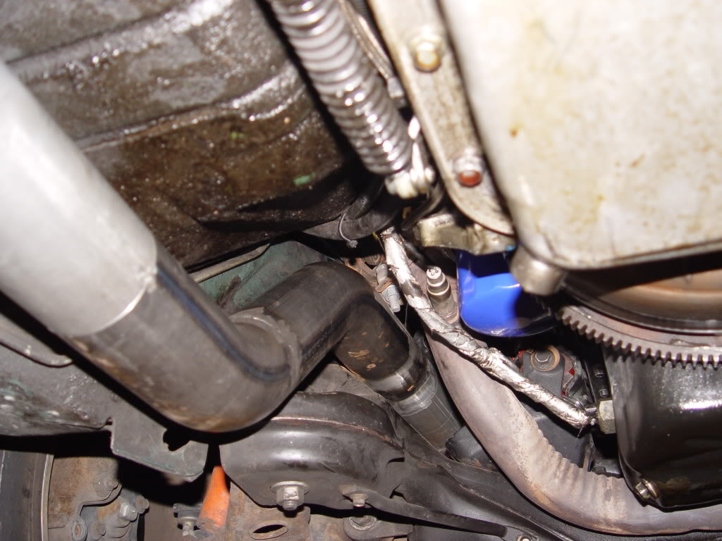
Bottom View.
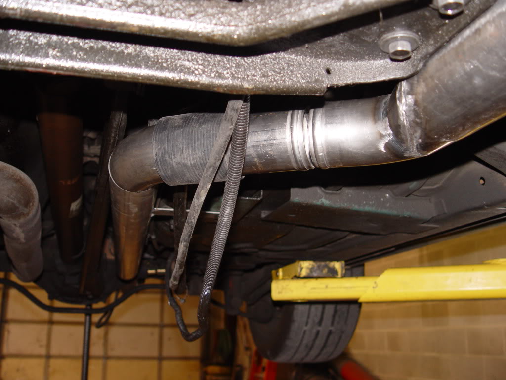
3" intake pipe going past motor.
Piping is 2.5" out of the 76mm turbo till the high-clearance transition pipe, then it's 3" to the intercooler, and 3.5" from intercooler to engine.
Here's the 2.5" to 3" transition pipe. It's the lowest point and has to get past a convertible brace. It's 3.5" pipe cut in half and capped (1.75" tall), so it's cross sectional area is about the same as the 2.5" tubing feeding into it.
Another view showing clearance restraints.
Bottom View.
3" intake pipe going past motor.
Last edited by MikeGyver; 11-17-2010 at 11:32 PM.
11-18-2010, 04:53 AM
#45
Registered User
Join Date: Dec 1999
Location: Upstate New York,USA
Posts: 1,791
Re: MikeGyver's Turbo 383 Build.
This is pretty much what I've been planning to do to get my ground clearance back, although I'm hoping to take my 3" down pipe into a flattened/ovalized 4" or 5" section, then retransition to the existing 3" past the tranny/crossmember. Right now, I'm using the piping from my Th350 setup. The TH350 has that area in front of the bellhousing where I put the pipe beneath the torque converter, then goes onto the generous space of the passenger side of the car. That gave me the ground clearance of a stock car! But with the T56 back in the car now, I had to drop it down a bit so now it's the lowest point on the car again 
Nice innovations Mike!
Nice innovations Mike!
Finished up all my new intake piping a couple days ago. Should be back from ceramic coating in a week or so.
Piping is 2.5" out of the 76mm turbo till the high-clearance transition pipe, then it's 3" to the intercooler, and 3.5" from intercooler to engine.
Here's the 2.5" to 3" transition pipe. It's the lowest point and has to get past a convertible brace. It's 3.5" pipe cut in half and capped (1.75" tall), so it's cross sectional area is about the same as the 2.5" tubing feeding into it.

Another view showing clearance restraints.
Piping is 2.5" out of the 76mm turbo till the high-clearance transition pipe, then it's 3" to the intercooler, and 3.5" from intercooler to engine.
Here's the 2.5" to 3" transition pipe. It's the lowest point and has to get past a convertible brace. It's 3.5" pipe cut in half and capped (1.75" tall), so it's cross sectional area is about the same as the 2.5" tubing feeding into it.
Another view showing clearance restraints.