
Logging wideband O2 with stock PCM and Datamaster – WRITEUP


Registered User
Joined: Aug 2006
Posts: 3,705
From: Kansas
Originally Posted by MANUAL
Optionally, the YELLOW (Analog out 1) and/or BROWN (Analog out 2) can be connected
to the analog inputs of other devices such as data loggers, ECUs, or gauges. If either one or
both of these wires are not being used isolate and tape the wire(s) out of the way. The default
analog outputs are as follows: Analog output one is 1.1V = 14 AFR and .1V = 15 AFR. This is
a simulated narrowband signal. Analog output two is setup as 0V = 7.35 AFR and 5V = 22.39
AFR.
Registered User
Joined: Jan 2007
Posts: 275

Registered User
Joined: Jul 2002
Posts: 1,193
From: San Diego, CA
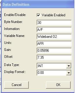
It will log all of the information and save it accordingly. Your tuner will have to program his custom data view with the information provided above to view it. The data is there, but the tuner must input the equation/parameters to view it.


Registered User
Joined: Dec 2005
Posts: 372
I am using this data to compose a similar setup with my FJO wideband controler and datamaster. I've run into a question when calculating the linear equation. You say that with the LC-1 the equation is AFR=3.008V+7.35.
My question is were did you sumize the 3.008 from? My FJO goes from 10.0 AFR to 20.0 AFR thus I am trying to calculate the new equation. If I know were you came up with the 3.0008 I can complete the equation. If 3.008 holds true in factoring in the correct gain and offset for both controlers I can then use the given equation.
Thanks for your input and GREAT thread!
Edit: Ahh yes my output analog signal will be from 0V to 5V.
Edit: I'm also having trouble figuring out how you derived .0196 from the equation AFR=3.008V+7.35. Could you please explain. THANKS.
Last edited by Airbornec507; Jun 16, 2008 at 11:39 AM.

Registered User
Joined: Feb 2000
Posts: 1,445
From: Seattle, WA
that's the slope of the regression line.
Slope = rise/run
Slope = (change in AFR)/(change in voltage) = 10/5 = 2
You can use 2 for your slope and 10 for the intercept (2v+10). The EXACT relationship should be in teh FJO literature or by contacting the company.
the "intercept" is the AFR indicated by 0 volts, the slope will be the gain in AFR per volt (which I estimated around 2 above).
Registered User
Joined: Dec 2005
Posts: 372
Ok so my equation looks like this: 2V+10. That makes sense. So my offset is 10 but to solve for the correct gain input I need to find out how you derived .0196 from your equation AFR=3.008V+7.35. This is how you came up with your gain.
"Replacing V with the integer above, we get AFR=(3.008*0.0196)*N + 7.35 which equals AFR=0.05896*N + 7.35 ; this function will convert raw data N to AFR."
How do I come up with my ".0196", figuratively speaking, to complete my equation for my final gain input into datamaster. Or are you stating that my gain is in fact right in front of my face: "2"?


Registered User
Joined: Feb 2000
Posts: 1,445
From: Seattle, WA
I wired up a simple DPST switch inline with the AC input. One position connects the the AC sensor to the PCM, the other position is the WBO2 input instead.
One note... if you're tuning the idle speed or cyclinder distribution do NOT use the WBO2 (or the AC) as the PCM will adapt for the extra load the aC is seeing... obviously if the AC isn't on this can cause minor rpm fluctuations that affects your idle speed.
Also, if you use a switch like I did, make sure you twist and solder the wires firmly, then paint the contacts with liquid insulation (rubber stuff you can get a Lowe's Hardware or the like) then wrap it in 3M Electrical Tape... keeping the contacts dry will prevent corrosion and help this be a nice long-term installation.
As for the 0.0196 question, that came from the idea of displaying AFR in the AC field in datamaster. I don't use datamaster myself, so I've never had to do it, but that factor is used to "adjust" your voltage to show up in the PSI reading of AC. Take the 2, multiply by 0.0196 and you'll get the actual factor you want to use in datamaster... this way the AC Pressure field will display your AFR directly as a PSI (though the decimal will be 1 off... like XXx.x instead of XX.xx, but that's as close as you'll get by using datamaster).
Registered User
Joined: Dec 2005
Posts: 372
Excellent! Thank you for your help. Now I don't have to run seperate laptops for each program in the car.
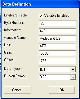
Edit: So for folks using the FJO data input would be same as your's with the following exceptions(be sure that the volts for the Aux output are from 0v to 5v for the calculations to work correctly. Also the min and max AFR set to 10 and 20 respectively) :
Offset = 10
Gain = .0392
Edit: So for folks using the FJO data input would be same as your's with the following exceptions(be sure that the volts for the Aux output are from 0v to 5v for the calculations to work correctly. Also the min and max AFR set to 10 and 20 respectively) :
Offset = 10
Gain = .0392
Last edited by Airbornec507; Jun 17, 2008 at 06:14 PM. Reason: New perameters for FJO Tuners through Datamaster

Registered User
Joined: Aug 2000
Posts: 1,071
From: Dallas,TX
After you have wired in the wideband controller and it is fully working, hook up the wideband controller analog output signal wire and the analog output ground wire to the relevant A/C pressure sensor connectors. The unused sensor connector can be used for a really clean install.
So I just need to look up which wire on the pressure sensor connector feeds the 5v signal into the PCM and connect that to my 0-5v out on the lc1 correct. Is that the only wire I need to tap into on the pressure sensor?
My LC1 has only 6 wires so I don't have an analog output ground like the LC1's with 7 wires.
If I can get this to work, this will help out my tuning capabilities alot!!!
Thanks everyone, good info!
Last edited by 97 RedSS; Jun 30, 2008 at 09:51 PM. Reason: added info