
Firewall Project

 Looks good though, and looks like quite a project! Look forward to the final product.

Thread Starter
Registered User
Joined: Jun 2006
Posts: 55
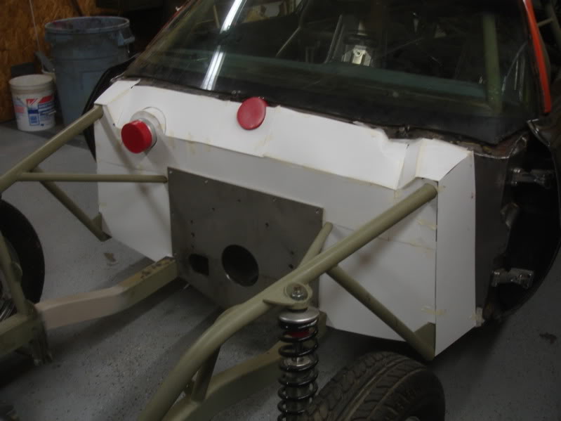
Before I start the firewall I wanted to get the English Wheel built. Ran into a little snag though. I made up the bottom anvil assembly last night. Cut the frame parts out today. Got a couple pcs. clamped together to weld.......and then stripped the threads out of the torch head on the TIG. and it's saturday.
There goes the weekend. ...............


There goes the weekend. ...............
Registered User
Joined: Sep 2009
Posts: 70
From: Enola, Pa
Bummer.
If you have any design or layout questions, Kerry Pinkerton over at AllMetalshaping.com is your man. He's like the rainman of English Wheels, and after using one of his, my Harbor Freight wheel seems like a piece of tin.
I seem to be the only fool I know of doing a widebody kit in steel, and he and those guys over there went out of their way to help me.
Thread Starter
Registered User
Joined: Jun 2006
Posts: 55
Bummer.
If you have any design or layout questions, Kerry Pinkerton over at AllMetalshaping.com is your man. He's like the rainman of English Wheels, and after using one of his, my Harbor Freight wheel seems like a piece of tin.
I seem to be the only fool I know of doing a widebody kit in steel, and he and those guys over there went out of their way to help me.
If you have any design or layout questions, Kerry Pinkerton over at AllMetalshaping.com is your man. He's like the rainman of English Wheels, and after using one of his, my Harbor Freight wheel seems like a piece of tin.
I seem to be the only fool I know of doing a widebody kit in steel, and he and those guys over there went out of their way to help me.


Thread Starter
Registered User
Joined: Jun 2006
Posts: 55
Got a little more done on the English wheel yesterday. A guy I talked to on the phone that builds E-Wheels said if I build one it needs to be very sturdy & needs a lot of adjustment built in. So, this is what I came up with for the top anvil. It's a little more complicated than it needs to be, but I had a couple old air actuated hydraulic cylinders laying around that I wanted to make use of. I got them for free probably about 30 years ago and finally decided it's time to use what's left of them. I found one of the cylinder housings was corroded through but the ram was still good & that's what I needed for the anvil adjuster. Too bad they are shot, the cylinders are all aluminum (except for the ram).
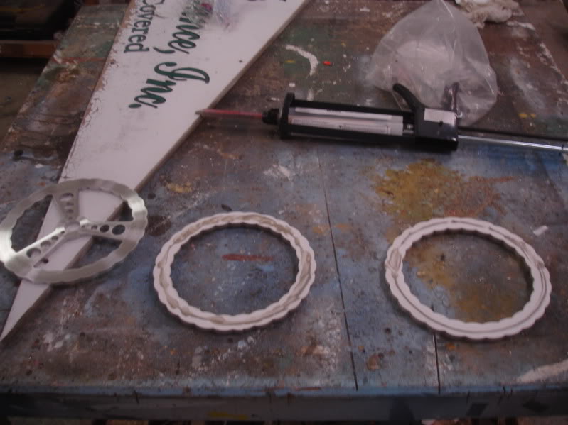
Anyway here's the deal. I cut a couple sleeves out of aluminum round stock for the rams.
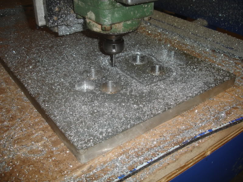
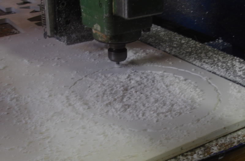
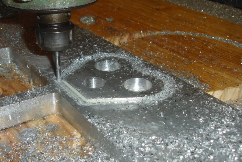
Cut a couple supports for the sleeves on the CNC
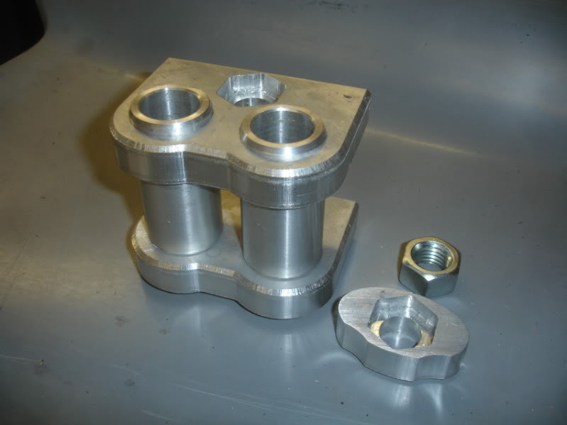
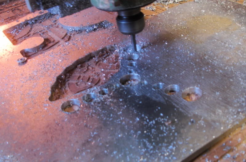
Parts pressed together. I didn't want the anvil assembly to rely on threads cut in aluminum, so I made this little pocket to hold a nut for the 3/4" ready rod that will be the adjusting screw.
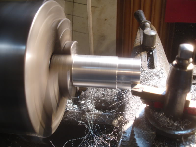
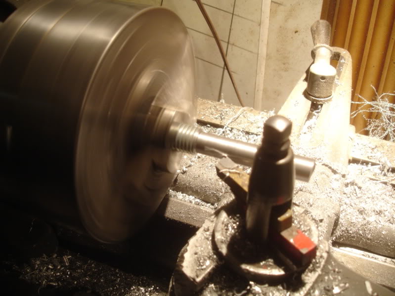
Turning part of the ready rod down to 5/8'' to make an adjuster out of it.
Anyway here's the deal. I cut a couple sleeves out of aluminum round stock for the rams.
Cut a couple supports for the sleeves on the CNC
Parts pressed together. I didn't want the anvil assembly to rely on threads cut in aluminum, so I made this little pocket to hold a nut for the 3/4" ready rod that will be the adjusting screw.
Turning part of the ready rod down to 5/8'' to make an adjuster out of it.
Thread Starter
Registered User
Joined: Jun 2006
Posts: 55
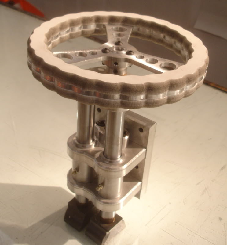
Thanks guys. This afternoon so I drew up & cut out the adjuster wheel for the E-Wheel.
Cut the hand grips out of 1/2" PVC.
1/4" aluminum for the wheel itself.
Used fusor auto body panel adhesive to glue it all together.
Like Norm Abram says ''I'll let it cook in the clamps overnight''.

Cut the hand grips out of 1/2" PVC.
1/4" aluminum for the wheel itself.
Used fusor auto body panel adhesive to glue it all together.
Like Norm Abram says ''I'll let it cook in the clamps overnight''.
Thread Starter
Registered User
Joined: Jun 2006
Posts: 55
Got a little more done tonight.
Cutting out the backing plate. The slots are to index the backing plate to the adjuster assembly.
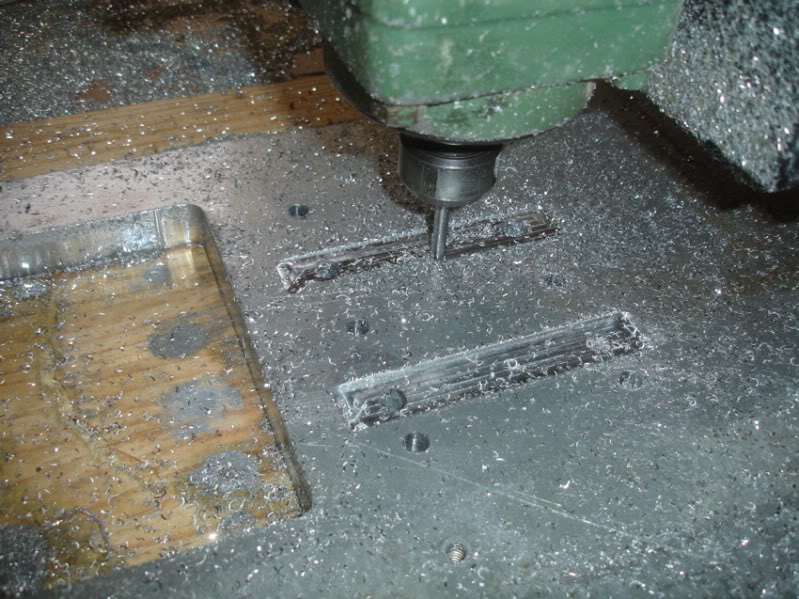
Cutting out the top cap that connects the ready rod to the rams.
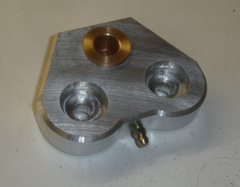
Top cap completed. The brass thrust bushings are pressed in from the top and bottom. They come about .020 short of touching each other. This allows grease to be pumped in from the grease fitting.
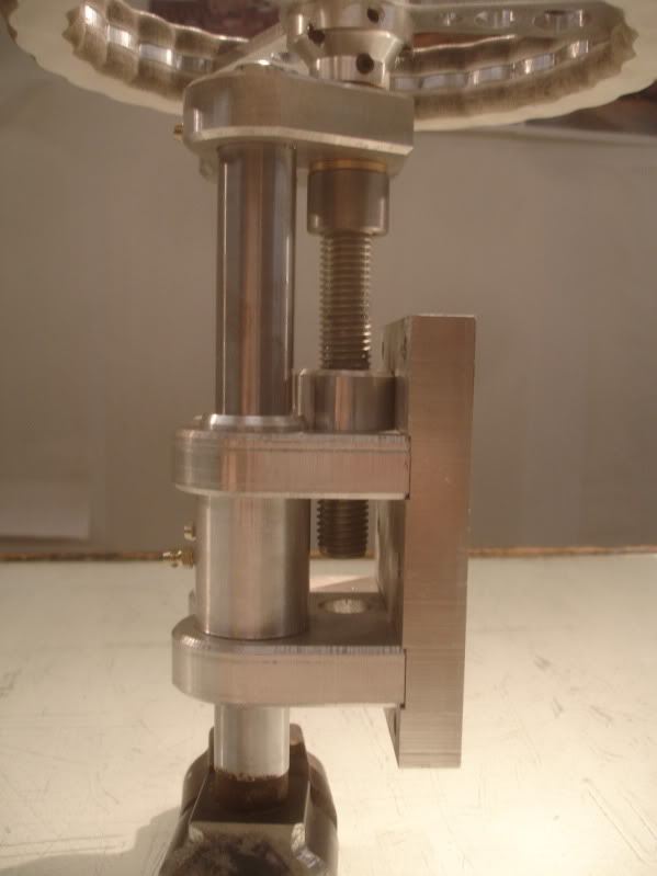
Assembly is pretty close to done. This shows the index slots that align the backing plate to the assembly.
I also added a grease fitting to each ram cylinder just to keep everything workin' smooth.
Cutting out the backing plate. The slots are to index the backing plate to the adjuster assembly.
Cutting out the top cap that connects the ready rod to the rams.
Top cap completed. The brass thrust bushings are pressed in from the top and bottom. They come about .020 short of touching each other. This allows grease to be pumped in from the grease fitting.
Assembly is pretty close to done. This shows the index slots that align the backing plate to the assembly.
I also added a grease fitting to each ram cylinder just to keep everything workin' smooth.
