
LT1 Alternator Relocation Write Up & Pics


Thread Starter
Registered User
Joined: Jul 2004
Posts: 118
From: Bolingbrook, IL
LT1 Alternator Relocation Write Up & Pics
I am finally done, test drove to and from work with no problems 
Pictures of install and fabrication: http://s100.photobucket.com/albums/m...GR/Alternator/
All in all I am pretty happy with the result, but it was a lot of thinking, cutting, fitting, re-fitting....re-fitting....re-fitting, bending....etc. I probably have 20 hours in this project. Way more than my converter install!
Here are the instructions:
Tools Required:
�Basic set of metric and standard sockets and wrenches.
�Sawzall or reciprocating saw.
�Dremel tool with cut-off wheels and grinding stones.
�Benzomatic torch w/ Mapp gas.
�Soldering gun or wire crimpers.
Additional Parts:
�Idler pulley (Pulley from A/C Delete Bracket works well)
�1-1/2� x 1-1/2� x 6� Piece of �L� steel
�1-1/2� x 1-1/2� x 6� Piece of flat stock steel
�New 6 Rib serpentine belt Dayco 52-1/2� (May Differ)
�Miscellaneous washers and bolts (Grade 8)
�Small length of wire to lengthen alternator plug (18 Gauge)
Disassembly Steps:
1) Get the front of the car up on jack stands so you can comfortably work from underneath and up top. I jacked up the front and rear.
2) Disconnect battery and remove for easier access to that side of the motor.
3) Remove serpentine belt.
4) Remove Alternator (ALT) connections followed by the alternator itself. I believe there are (3-4) 13mm bolts holding it in place.
5) Disconnect the Power Steering (PS) fluid hose and PS hard line connections to the pump. Remove (2) 10mm bolts, they are accessed through the PS pulley, so you will need a long socket or extension.
6) Remove the front sway bar and end-links to gain access to the AC compressor.
7) Remove Air Conditioning (AC) Compressor lines, rear bracket, and compressor unit. There are (3) 13mm bolts on the front of the unit.
8) Remove the spark plug wires that route along the accessory bracket.
9) Remove the (4) 14mm bolts holding the Accessory Bracket (AB) to the passenger side cylinder head and block and pull the accessory bracket out of the car.
10) Remove the (2) 10mm belt tensioner bolts and tensioner.
Ref 100_3332.jpg http://i100.photobucket.com/albums/m...r/100_3332.jpg
Bracket Modification/Fabrication:
A) Cut AB as needed to get the ALT as close to the bracket as possible.
Ref 100_3349.jpg http://i100.photobucket.com/albums/m...r/100_3349.jpg
Ref 100_3352.jpg http://i100.photobucket.com/albums/m...r/100_3352.jpg
Ref 100_3368.jpg http://i100.photobucket.com/albums/m...r/100_3368.jpg
Ref 100_3366.jpg http://i100.photobucket.com/albums/m...r/100_3366.jpg
Ref 100_3372.jpg http://i100.photobucket.com/albums/m...r/100_3372.jpg
B) Make additional cuts to the AB as needed to allow the spark plug wires easy access to the Optispark.
Ref 100_3383.jpg http://i100.photobucket.com/albums/m...r/100_3383.jpg
Ref 100_3384.jpg http://i100.photobucket.com/albums/m...r/100_3384.jpg
C) Cut an appropriate length of 1-1/2� x 1-1/2� �L� channel to create the bracket that will bolt to the AB and back of the ALT.
D) Drill 1 hole large enough to run a bolt through the top hole of the alternator so that is can pass through the bracket and be bolted from the back. I used the longest 13mm bolt which held the ALT in place up top.
E) Drill (2) 5/16� Holes through the AB and L-Channel. These holes will allow the L-channel to be bolted to the AB. I used (2) 5/16� x 1� Grade 8 Hardware with washers and lock nuts.
Ref 100_3385.jpg http://i100.photobucket.com/albums/m...r/100_3385.jpg
Ref 100_3389.jpg http://i100.photobucket.com/albums/m...r/100_3389.jpg
Ref 100_3388.jpg http://i100.photobucket.com/albums/m...r/100_3388.jpg
F) Cut an appropriate length of Flat Stock Steel approximately 2� x 6�to create the extension bracket that will bolt to the side of the engine block and back of the ALT.
Ref 100_3408.jpg http://i100.photobucket.com/albums/m...r/100_3408.jpg
G) Drill (2) 5/16� Holes through the flat stock. These holes will allow the flat stock to be bolted to the Block Bracket. I used (2) 5/16� x 1� Grade 8 Hardware with washers and lock nuts.
H) Drill (1) additional hole to bolt flat stock to the back of the alternator. Washers will be needed to fill up some of the gap between the bracket and alternator. Refer to picture above.
I) It is also possible that (1) ear on the alternator will need to be cut a small amount. This will help with the serpentine belt alignment. I felt it necessary to cut the ear on the alternator because that hole does not have threads, and the AB does.
Ref 100_3351.jpg http://i100.photobucket.com/albums/m...r/100_3351.jpg
J) Disassemble all brackets and parts, prep and spray paint or coat as you wish.
In Car Assembly:
1) Bolt ALT to AB and bolt motor with (4) 14mm bolts.
2) Bolt PS Pump to AB and tighten the (2) 10mm PS bolts. Connect the PS hard line to the threaded hole in the pump and tighten. Make sure you do not lose the o-ring.
3) Bending or heating of the hard line may be needed in order to route the PS hard line correctly around the ALT and down to the PS Rack. This took quite a bit of trial and error in my application. A wire coat hanger can be bent and used as a good reference. I used a Benzomatic torch with Mapp gas to heat the tubing in order to bend.
4) Connect the other end of the PS hard line to the steering rack and tighten.
5) Lengthen the ALT connection wire about 6�-8�. I used solder and electrical tape and hid the wire in the loom before routing it down to make the connection to the ALT.
6) Route your Spark Plug wires down to the Optispark and connect. Make sure the correct wires are on the correct leads.
7) Connect the large rubber PS reservoir hose to the PS pump. I used a new hose clamp for this.
8) Bolt in your idler pulley to the top of the AB and tighten.
9) Install tensioner and tighten (2) 10mm bolts.
10) Route your serpentine belt. Check for interference between any hoses, wires, or objects.
11) Re-fill PS reservoir as needed
12) Re-Install front sway bar including endlinks.
13) Re-Install battery and connect cables.
14) Turn over motor and check for leaks, sounds, belt clearance. Add fluids if necessary. Also have someone blip the throttle a few times to make sure the alternator does not contact the frame.
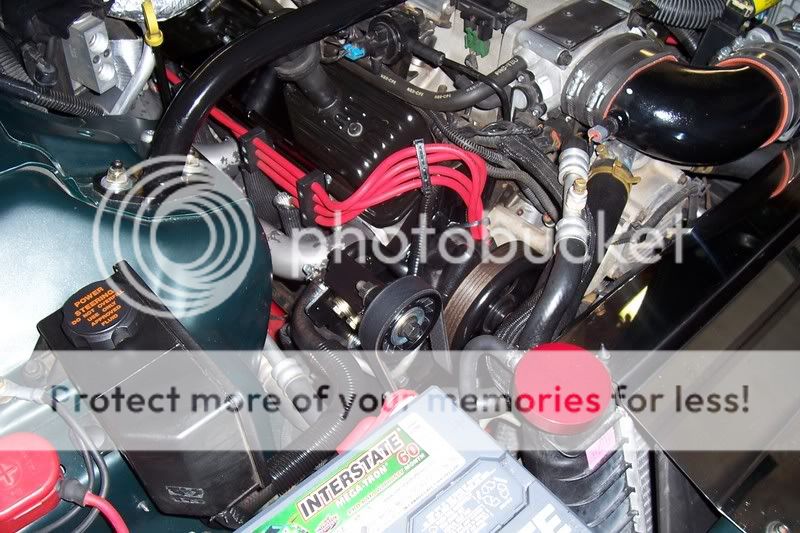
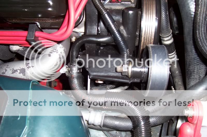
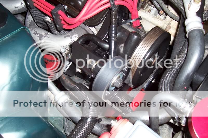
Finished Results:
Ref 100_3401.jpg
Ref 100_3402.jpg
Ref 100_3403.jpg
Ref 100_3404.jpg

Pictures of install and fabrication: http://s100.photobucket.com/albums/m...GR/Alternator/
All in all I am pretty happy with the result, but it was a lot of thinking, cutting, fitting, re-fitting....re-fitting....re-fitting, bending....etc. I probably have 20 hours in this project. Way more than my converter install!
Here are the instructions:
Tools Required:
�Basic set of metric and standard sockets and wrenches.
�Sawzall or reciprocating saw.
�Dremel tool with cut-off wheels and grinding stones.
�Benzomatic torch w/ Mapp gas.
�Soldering gun or wire crimpers.
Additional Parts:
�Idler pulley (Pulley from A/C Delete Bracket works well)
�1-1/2� x 1-1/2� x 6� Piece of �L� steel
�1-1/2� x 1-1/2� x 6� Piece of flat stock steel
�New 6 Rib serpentine belt Dayco 52-1/2� (May Differ)
�Miscellaneous washers and bolts (Grade 8)
�Small length of wire to lengthen alternator plug (18 Gauge)
Disassembly Steps:
1) Get the front of the car up on jack stands so you can comfortably work from underneath and up top. I jacked up the front and rear.
2) Disconnect battery and remove for easier access to that side of the motor.
3) Remove serpentine belt.
4) Remove Alternator (ALT) connections followed by the alternator itself. I believe there are (3-4) 13mm bolts holding it in place.
5) Disconnect the Power Steering (PS) fluid hose and PS hard line connections to the pump. Remove (2) 10mm bolts, they are accessed through the PS pulley, so you will need a long socket or extension.
6) Remove the front sway bar and end-links to gain access to the AC compressor.
7) Remove Air Conditioning (AC) Compressor lines, rear bracket, and compressor unit. There are (3) 13mm bolts on the front of the unit.
8) Remove the spark plug wires that route along the accessory bracket.
9) Remove the (4) 14mm bolts holding the Accessory Bracket (AB) to the passenger side cylinder head and block and pull the accessory bracket out of the car.
10) Remove the (2) 10mm belt tensioner bolts and tensioner.
Ref 100_3332.jpg http://i100.photobucket.com/albums/m...r/100_3332.jpg
Bracket Modification/Fabrication:
A) Cut AB as needed to get the ALT as close to the bracket as possible.
Ref 100_3349.jpg http://i100.photobucket.com/albums/m...r/100_3349.jpg
Ref 100_3352.jpg http://i100.photobucket.com/albums/m...r/100_3352.jpg
Ref 100_3368.jpg http://i100.photobucket.com/albums/m...r/100_3368.jpg
Ref 100_3366.jpg http://i100.photobucket.com/albums/m...r/100_3366.jpg
Ref 100_3372.jpg http://i100.photobucket.com/albums/m...r/100_3372.jpg
B) Make additional cuts to the AB as needed to allow the spark plug wires easy access to the Optispark.
Ref 100_3383.jpg http://i100.photobucket.com/albums/m...r/100_3383.jpg
Ref 100_3384.jpg http://i100.photobucket.com/albums/m...r/100_3384.jpg
C) Cut an appropriate length of 1-1/2� x 1-1/2� �L� channel to create the bracket that will bolt to the AB and back of the ALT.
D) Drill 1 hole large enough to run a bolt through the top hole of the alternator so that is can pass through the bracket and be bolted from the back. I used the longest 13mm bolt which held the ALT in place up top.
E) Drill (2) 5/16� Holes through the AB and L-Channel. These holes will allow the L-channel to be bolted to the AB. I used (2) 5/16� x 1� Grade 8 Hardware with washers and lock nuts.
Ref 100_3385.jpg http://i100.photobucket.com/albums/m...r/100_3385.jpg
Ref 100_3389.jpg http://i100.photobucket.com/albums/m...r/100_3389.jpg
Ref 100_3388.jpg http://i100.photobucket.com/albums/m...r/100_3388.jpg
F) Cut an appropriate length of Flat Stock Steel approximately 2� x 6�to create the extension bracket that will bolt to the side of the engine block and back of the ALT.
Ref 100_3408.jpg http://i100.photobucket.com/albums/m...r/100_3408.jpg
G) Drill (2) 5/16� Holes through the flat stock. These holes will allow the flat stock to be bolted to the Block Bracket. I used (2) 5/16� x 1� Grade 8 Hardware with washers and lock nuts.
H) Drill (1) additional hole to bolt flat stock to the back of the alternator. Washers will be needed to fill up some of the gap between the bracket and alternator. Refer to picture above.
I) It is also possible that (1) ear on the alternator will need to be cut a small amount. This will help with the serpentine belt alignment. I felt it necessary to cut the ear on the alternator because that hole does not have threads, and the AB does.
Ref 100_3351.jpg http://i100.photobucket.com/albums/m...r/100_3351.jpg
J) Disassemble all brackets and parts, prep and spray paint or coat as you wish.
In Car Assembly:
1) Bolt ALT to AB and bolt motor with (4) 14mm bolts.
2) Bolt PS Pump to AB and tighten the (2) 10mm PS bolts. Connect the PS hard line to the threaded hole in the pump and tighten. Make sure you do not lose the o-ring.
3) Bending or heating of the hard line may be needed in order to route the PS hard line correctly around the ALT and down to the PS Rack. This took quite a bit of trial and error in my application. A wire coat hanger can be bent and used as a good reference. I used a Benzomatic torch with Mapp gas to heat the tubing in order to bend.
4) Connect the other end of the PS hard line to the steering rack and tighten.
5) Lengthen the ALT connection wire about 6�-8�. I used solder and electrical tape and hid the wire in the loom before routing it down to make the connection to the ALT.
6) Route your Spark Plug wires down to the Optispark and connect. Make sure the correct wires are on the correct leads.
7) Connect the large rubber PS reservoir hose to the PS pump. I used a new hose clamp for this.
8) Bolt in your idler pulley to the top of the AB and tighten.
9) Install tensioner and tighten (2) 10mm bolts.
10) Route your serpentine belt. Check for interference between any hoses, wires, or objects.
11) Re-fill PS reservoir as needed
12) Re-Install front sway bar including endlinks.
13) Re-Install battery and connect cables.
14) Turn over motor and check for leaks, sounds, belt clearance. Add fluids if necessary. Also have someone blip the throttle a few times to make sure the alternator does not contact the frame.
Finished Results:
Ref 100_3401.jpg
Ref 100_3402.jpg
Ref 100_3403.jpg
Ref 100_3404.jpg


Thread
Thread Starter
Forum
Replies
Last Post
Gtpguy
General 1967-2002 F-Body Tech
48
Jan 26, 2015 04:50 PM