
pics of chambers and bowl area


Thread Starter
Registered User
Joined: Nov 2004
Posts: 373
From: Lawrence, KS
pics of chambers and bowl area
hey guys just so everyone knows ive used the search and exhuasted all the pictures i could find, but id really like to see if anyone has anymore. id like pics of only LT1 heads obviously. thanks for any help and i hope to see some pics. o and the reason im trying to find them is im doing my own heads and would like to compare. 

Registered User
Joined: Mar 2001
Posts: 2,521
From: Costa Mesa, CA
Re: pics of chambers and bowl area
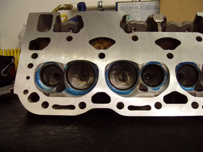
I know they aren't in great detail, but those are the three best ones I can come up with now. That was my second attempt at some homeporting and it seems to have come out pretty well.
Be careful in the exhaust bowl area or you'll port into the water jacket and end up removing your new engine to take the head off because heads studs will prevent you from doing it in the car. Don't ask me how I know

Thread Starter
Registered User
Joined: Nov 2004
Posts: 373
From: Lawrence, KS
Re: pics of chambers and bowl area
thanks thats awesome. did you ever have those flowed? also did you grind the exhuast guide completely flat?  ive never seen one done like that. is that common? im keeping mine on a mild port, clean everything up, smooth the guides and try to help with what i think the "flow" would like to do.
ive never seen one done like that. is that common? im keeping mine on a mild port, clean everything up, smooth the guides and try to help with what i think the "flow" would like to do.


Registered User
Joined: Mar 2001
Posts: 2,521
From: Costa Mesa, CA
Re: pics of chambers and bowl area
Originally Posted by T/A Racer
thanks thats awesome. did you ever have those flowed? also did you grind the exhuast guide completely flat? ive never seen one done like that. is that common? im keeping mine on a mild port, clean everything up, smooth the guides and try to help with what i think the "flow" would like to do.
ive never seen one done like that. is that common? im keeping mine on a mild port, clean everything up, smooth the guides and try to help with what i think the "flow" would like to do.Intake flowed 243 cfm @ .550 and 242.9 cfm @.600. This was with a 2.00" Manley RaceFlo valve, before a competition valve job.
Exhaust flowed right at 180 @.600. This was with a stock exhaust valve, before a competition valve job and back cut on the valve.
Not exactly scorching hot numbers, but considering the work was free and I got some pretty decent mid lift numbers out of the heads I'm happy. I just can't wait to see how the new combo works out.
Registered User
Joined: Jun 2001
Posts: 3,737
From: waterford, MI - USA
Re: pics of chambers and bowl area


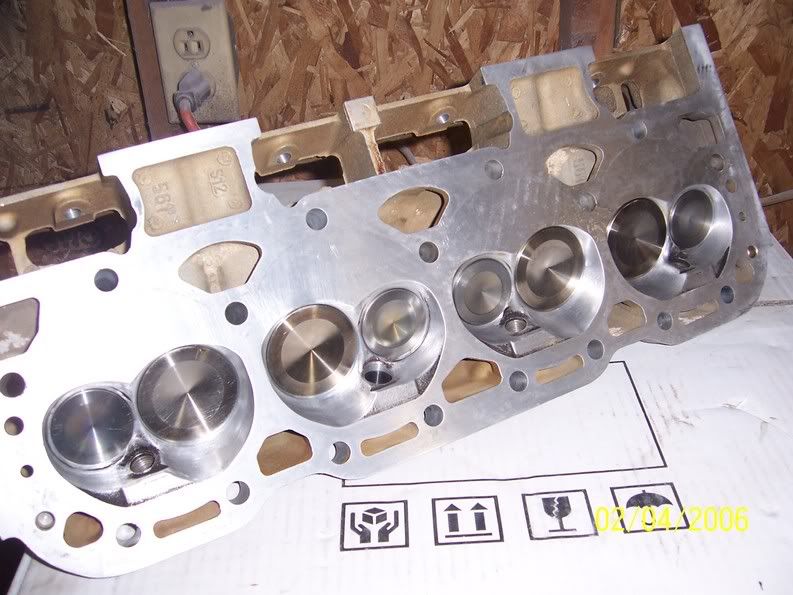
here's a few of mine. first attempt. they came out pretty good. bout the same as the other fella's as far as flow goes. but I had stock valves. later I did smooth off the valves a little on a bench grinder. just took off the edge or "hump" the air would have to flow over to get into the cyl.s at low lift especially. but stayed away from the seat. but I wish I could have just bought some good aftermarket valves. not enough funds at the time though. next set I do for my Z will have aftermarket valves in them forsure.
Registered User
Joined: Jun 2001
Posts: 3,737
From: waterford, MI - USA
Re: pics of chambers and bowl area
http://pg.photos.yahoo.com/ph/irocss...de.jpg&.src=ph
actually a much better pic of after I finished them. the other pic was not quite finished yet.
actually a much better pic of after I finished them. the other pic was not quite finished yet.
Registered User
Joined: Mar 2001
Posts: 2,521
From: Costa Mesa, CA
Re: pics of chambers and bowl area
Originally Posted by IrocSS85
but I wish I could have just bought some good aftermarket valves. not enough funds at the time though. next set I do for my Z will have aftermarket valves in them forsure.
Registered User
Joined: Jun 2001
Posts: 3,737
From: waterford, MI - USA
Re: pics of chambers and bowl area
cool. remember how much better the intake valve flowed? wonder how the stock exh. valve could have poss. flowed better then the manley valve? also Ive heard a multiangle valve job does wonders for low lift numbers. I used a drill and lapping compound to clean off the faces of my valves and seats. seemed to clean up really good, but there is only like 2 angles there if I remember right.
Registered User
Joined: Mar 2001
Posts: 2,521
From: Costa Mesa, CA
Re: pics of chambers and bowl area
The Manley intake valve flowed 4-5 cfm better than the stocker did at most. I think the deal with the exhaust valve is that with the stock one being smaller it shrouded less in the chamber.

Registered User
Joined: Jan 2003
Posts: 14
Re: pics of chambers and bowl area
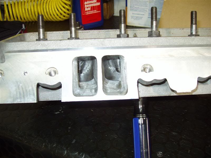
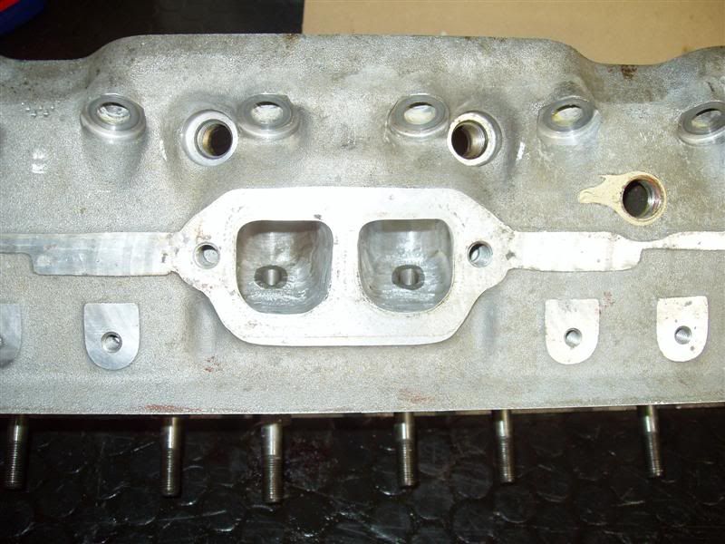
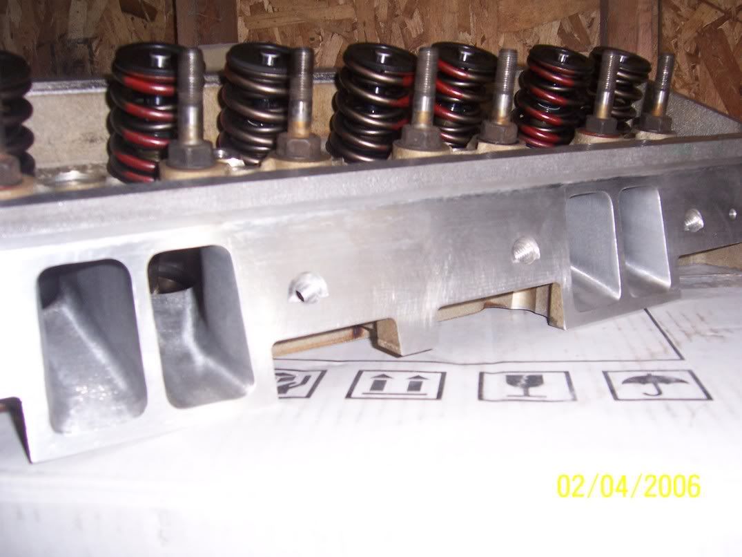
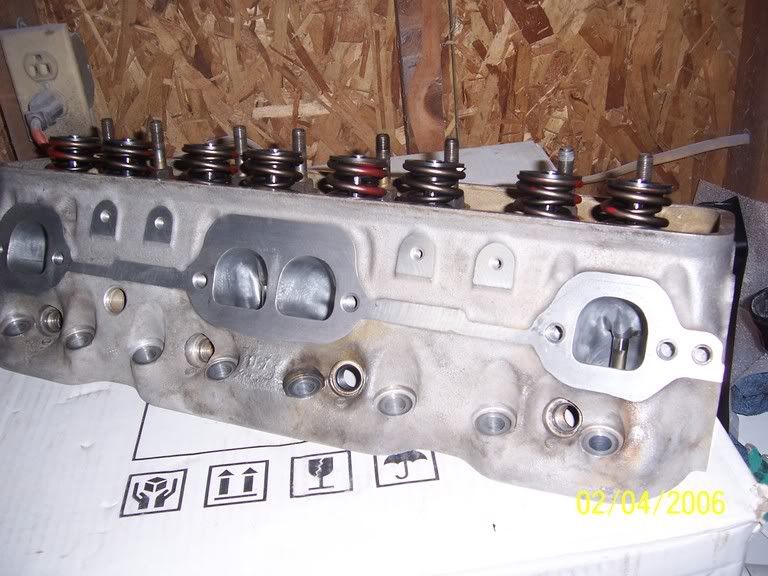
Here are a couple of pics of my home port, an "almost finished" port shot and a final shot of the bowls. These peaked at 249cfm @.550, a decent improvement considering only about 2-3cc of material has been removed from total port volume. I think you will get a little more flow by raising the roofs, but I pretty much left them alone.
http://i38.photobucket.com/albums/e1...kebosscut2.jpg
http://i38.photobucket.com/albums/e1...bowlfinal2.jpg
http://i38.photobucket.com/albums/e1...kebosscut2.jpg
http://i38.photobucket.com/albums/e1...bowlfinal2.jpg


Registered User
Joined: Mar 2001
Posts: 2,521
From: Costa Mesa, CA
Re: pics of chambers and bowl area
Originally Posted by chevsen

Registered User
Joined: Dec 2004
Posts: 968
From: Wichita, KS
Re: pics of chambers and bowl area
Here ya go...
edit: I thought I might add a little info on these:
http://web.camaross.com/forums/showt...highlight=Flow
edit: I thought I might add a little info on these:
http://web.camaross.com/forums/showt...highlight=Flow
Last edited by Colin91Z; Feb 7, 2006 at 11:47 AM.