installing trans temp gauge...

 12-28-2006, 12:45 AM
#32
Registered User
Thread Starter
Join Date: Feb 2006
Location: King of Prussia, PA
Posts: 928
with the lack of knowledge that you guys are witnessing.. do you think itd be a good idea to focus on the electrical aspect of all this and when i take my car to be inspected.. pay them to install the fitting with the sender? shouldnt be that much right?
12-28-2006, 07:30 AM
#33
Registered User
Join Date: May 2006
Location: Pothole, Ohio
Posts: 559
I found the job not too difficult. I don't know you or what tools you have on hand but for me it never occurred to me to have someone else do it.
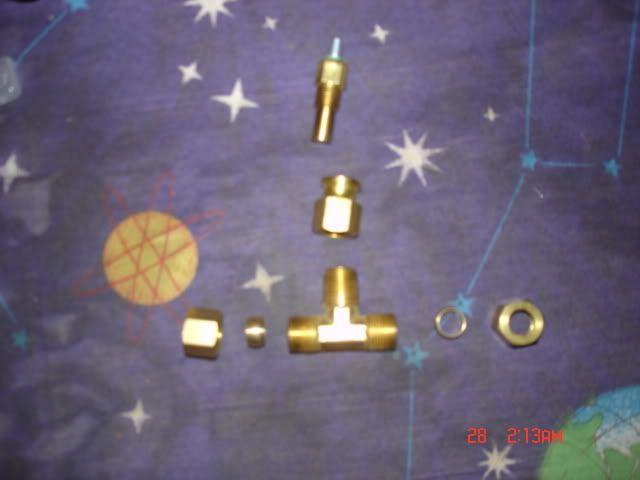
As for the parts you have:
Yes, those compression fittings are for the metal line. A better way to install the Tee fitting so don't cut your rubber section; cut the steel line instead and your sensor will be automatically grounded. You just need to pick a spot and clean it well with steel wool and cut it with a tubing cutter. I would manually deburr the inside of the line afterwards as a tubing cutter closes the inside diameter a little. I have a hand de-burring blade for this; something everyone should have. You can find these at Sears I believe. Just be careful to remove the metal that you remove. A magnet, care and some imagination will help to make sure no steel shaving goes in either direction within the line.

As for the fluid loss, I lost a tablespoon or less when I did mine. The flow is slow after the line is opened. The Tee now gives you an opportunity to flush your system after the installation if you care to do it. With the sensor out and the engine started you can extract a quart or two from the TC and purge fluid that would normally not get drained when doing a regular fluid / filter change. You just need to be careful to get back to the correct levels when finished. Which brings to mind that my B&M cooler required a little more fluid to be added after all was said and done. I think a pint or so.
As for the parts you have:
Yes, those compression fittings are for the metal line. A better way to install the Tee fitting so don't cut your rubber section; cut the steel line instead and your sensor will be automatically grounded. You just need to pick a spot and clean it well with steel wool and cut it with a tubing cutter. I would manually deburr the inside of the line afterwards as a tubing cutter closes the inside diameter a little. I have a hand de-burring blade for this; something everyone should have. You can find these at Sears I believe. Just be careful to remove the metal that you remove. A magnet, care and some imagination will help to make sure no steel shaving goes in either direction within the line.
As for the fluid loss, I lost a tablespoon or less when I did mine. The flow is slow after the line is opened. The Tee now gives you an opportunity to flush your system after the installation if you care to do it. With the sensor out and the engine started you can extract a quart or two from the TC and purge fluid that would normally not get drained when doing a regular fluid / filter change. You just need to be careful to get back to the correct levels when finished. Which brings to mind that my B&M cooler required a little more fluid to be added after all was said and done. I think a pint or so.
Last edited by 01Z; 12-28-2006 at 07:47 AM. Reason: adding content
12-28-2006, 07:42 AM
#34
Registered User
Join Date: May 2006
Location: Pothole, Ohio
Posts: 559
Here's another tubing cutter for tight spaces. It costs less too.

As for the size of the barbs in case you have to use the rubber line, I think mine were 1/4" but I am not sure. I think I bought two sets so I wouldn't have to drive back to the hardware store. So either they are 1/4" or 5/16" but it is a good idea to cut the hose and measure it. I used a couple of clean bolts to plug everything up until I got back from the store. I am definitely a shade tree mechanic so there are always better ways than mine.
As for the size of the barbs in case you have to use the rubber line, I think mine were 1/4" but I am not sure. I think I bought two sets so I wouldn't have to drive back to the hardware store. So either they are 1/4" or 5/16" but it is a good idea to cut the hose and measure it. I used a couple of clean bolts to plug everything up until I got back from the store. I am definitely a shade tree mechanic so there are always better ways than mine.
12-28-2006, 01:04 PM
#36
Registered User
Join Date: May 2006
Location: Pothole, Ohio
Posts: 559
You might only need to cut the line and not remove a section. Things are pretty flexible under there and those steel lines bend around easily. If you don't mind a bulge or slight loop you can get away with one cut. Good luck with this. Always fun stuff when you can add to the car and not have to repair it.
12-28-2006, 03:18 PM
#37
Registered User
Thread Starter
Join Date: Feb 2006
Location: King of Prussia, PA
Posts: 928
help! I cut the metal tube to put the fitting on.. the big one is loose when i put it on and slides around.. the little one i cant really get on! It feels like it should slide in but i think i mishapened the tube a little.. i really gotta get this together i have to take the car in tomorrow for inspection and the sun is going down!
12-28-2006, 04:49 PM
#39
Registered User
Thread Starter
Join Date: Feb 2006
Location: King of Prussia, PA
Posts: 928
okay i think its a wiring issue. when i turn the car on.. needle goes way below 100.. then i turn the lights on.. gauge light works, dash lights and radio clock... non existent. Then when i turn the car off and turn the lights down to parking lights the gauge jumps up to 220. but the cars off... what did i do wrong with my wiring?
12-28-2006, 05:02 PM
#40
Registered User
Join Date: May 2006
Location: Pothole, Ohio
Posts: 559
On my Stewart Warner gauge, the temperature doesn't get high enough for quite while to make the needle move. As for yours pegging to the max, you probably have the 12 volt power going to the wrong post. Understand that the sensor changes resistance as the temperature rises and falls. When the sensor is hot the voltage increases in the circuit. This is where a voltmeter and continuity tester comes in handy.
Once again, if you have 12 volts from the fuse block wired to the sensor post on the gauge you will see it peg immediately. If you have it wired to the wrong side of a switch you will also get full voltage at the wrong place. You have to understand how the gauge and sensor work and then figure out what wires you are hooking to each post. It is easy to connect the 12 volts for the light to the sensor post. I have done it in the past. Check your instructions for the gauge and trace your wires back to their sources. You can figure this out but you have to be thorough.
Once again, if you have 12 volts from the fuse block wired to the sensor post on the gauge you will see it peg immediately. If you have it wired to the wrong side of a switch you will also get full voltage at the wrong place. You have to understand how the gauge and sensor work and then figure out what wires you are hooking to each post. It is easy to connect the 12 volts for the light to the sensor post. I have done it in the past. Check your instructions for the gauge and trace your wires back to their sources. You can figure this out but you have to be thorough.
12-28-2006, 05:04 PM
#41
Registered User
Thread Starter
Join Date: Feb 2006
Location: King of Prussia, PA
Posts: 928
its wired wrong i fixed it.. now the only problem is that i have no dash lights, clock, or head lights.. something with the way i hooked it to the fuse maybe?
can you show me a pic of how you had yours hooked up? to the fuses and wires
can you show me a pic of how you had yours hooked up? to the fuses and wires
Last edited by nodnarb481; 12-28-2006 at 05:28 PM.
12-28-2006, 06:02 PM
#43
Registered User
Join Date: May 2006
Location: Pothole, Ohio
Posts: 559
It just takes the slightest contact between + and - in a tiny moment of time to blow a fuse.
Keep looking at the wiring diagram and understand how it works. You're almost there. Just trace your wiring so you have ground and power to the gauge and make certain you have the sensor wire going to the correct post on the gauge. Keep in mind the gauge light is a completely separate circuit. Your instructions probably tell you the ground has to be to the chassis and not the engine but double check that.
Keep looking at the wiring diagram and understand how it works. You're almost there. Just trace your wiring so you have ground and power to the gauge and make certain you have the sensor wire going to the correct post on the gauge. Keep in mind the gauge light is a completely separate circuit. Your instructions probably tell you the ground has to be to the chassis and not the engine but double check that.
12-28-2006, 09:11 PM
#44
Registered User
Thread Starter
Join Date: Feb 2006
Location: King of Prussia, PA
Posts: 928
it says find a chasis ground.. i found a bolt holding a bar that goes around the steering column and bolts to some metal... thing.. and i grounded it there. im going to go put this new fuse in and see if im done