installing trans temp gauge...


 12-27-2006, 10:51 AM
#19
Registered User
Thread Starter
Join Date: Feb 2006
Location: King of Prussia, PA
Posts: 928
okay nice...as far as using the volt meter... mine has all kinds of settings.. DV volts : 10v 100v 250v etc.. and do i need to strip a wire to connect the lead to the copper inside to get a reading?
12-27-2006, 11:00 AM
#20
Registered User
Thread Starter
Join Date: Feb 2006
Location: King of Prussia, PA
Posts: 928
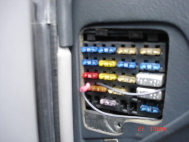
here is another picture.. ignoring the power hook up he has.. do you have any idea what that orange -5- he has the light hooked up to? it looks like he just shoved it in there..
http://ken.lowrance.com/projects/TransCooler/
click fuse block wiring on side
http://ken.lowrance.com/projects/TransCooler/
click fuse block wiring on side
 12-27-2006, 11:47 AM
#22
Administrator
Join Date: Nov 1998
Location: Hell was full so they sent me to NJ
Posts: 70,648
The links goes to an install on a Z28. The fuse panel in the Camaros is "right side up"..... the one in the Firebirds is "upside down" (why would they do something like that  ). He has the one orange wire in the same slot mine is in.
The -5- fuse is the "IP DIMMER" fuse. That's another place you can tie in, but you need to do something more positive than just push the wire in there. I've seen people do that by pulling the fuse out, heating the side of the fuse and pushing the wire through the plastic into contact with the metal blade. You have to make sure you attach it to the "load" side of the fuse, or the gauge connection will not be protected by the fuse. And if the fuse ever blows, you have to make up a fuse with a new connection. If the space in the fuse box wasn't so limited, there is an adapter that will press into the fuse box in place of the fuse, then have two external fuses and two connections for loads.
The reason my connection is made the way it is, without the nylon extension on the crimp-on connector, is so the cover will go back on the panel.
). He has the one orange wire in the same slot mine is in.The -5- fuse is the "IP DIMMER" fuse. That's another place you can tie in, but you need to do something more positive than just push the wire in there. I've seen people do that by pulling the fuse out, heating the side of the fuse and pushing the wire through the plastic into contact with the metal blade. You have to make sure you attach it to the "load" side of the fuse, or the gauge connection will not be protected by the fuse. And if the fuse ever blows, you have to make up a fuse with a new connection. If the space in the fuse box wasn't so limited, there is an adapter that will press into the fuse box in place of the fuse, then have two external fuses and two connections for loads.
The reason my connection is made the way it is, without the nylon extension on the crimp-on connector, is so the cover will go back on the panel.
12-27-2006, 11:51 AM
#23
Registered User
Thread Starter
Join Date: Feb 2006
Location: King of Prussia, PA
Posts: 928
how can i tell which side is the load side?.. ii had to use a male connector for the IGN by the way.. the female wouldnt work and the male slipped right in because the inside is like 0's pressed against eachother sideways like an 8 so i slipped it between the two o's.
I just put the wire on the fuse and pushed them in together. thats not going to work is it? and how can i tell which side is the load side?
finally what should i ground it to?
I just put the wire on the fuse and pushed them in together. thats not going to work is it? and how can i tell which side is the load side?
finally what should i ground it to?
Last edited by nodnarb481; 12-27-2006 at 11:56 AM.
12-27-2006, 02:42 PM
#24
Administrator
Join Date: Nov 1998
Location: Hell was full so they sent me to NJ
Posts: 70,648
Pull the fuse out. Ground the black volt meter lead. Touch the red volt meter lead to each side of the metal that the fuse slides into. The one with +12V is the power supply side. The one with 0V is the load side.
12-27-2006, 03:27 PM
#26
Registered User
Thread Starter
Join Date: Feb 2006
Location: King of Prussia, PA
Posts: 928
okay so the ground wire is grounded to a bolt near the steering column.. the power wire is in the place you told me, the light wire is in the IP Dimmer Fuse. Now i need to install the sender unit. THe wire is run through the PCM grommit into the engine compartment. I just need to know what tube is the return line and how to properly install a "properly grounded sender" on this line without fluid exploding out all over the place
12-27-2006, 06:28 PM
#27
Registered User
Join Date: May 2006
Location: Pothole, Ohio
Posts: 559
If I might add something else. Don't use the plug in the side of the tranny for the sensor. It is a dead end and all you will be reading is the transmission case temperature. The correct place to put the sensor is the fluid hot line that runs to the radiator or transmission cooler. It will be the top line with rubber hose section. I cut the hose and built a barbed adapter for the sensor. I had to solder a ground wire from/to the sensor body. I just cleaned a section of the transmission line and soldered to it.
Last edited by 01Z; 12-27-2006 at 08:56 PM.
12-27-2006, 08:54 PM
#28
Registered User
Thread Starter
Join Date: Feb 2006
Location: King of Prussia, PA
Posts: 928
thank you for your help.. i am not doing the pressure port im going to tap the line.. but i dont understand how to do it.. I understand where to cut but after that.. i have a brass T-fitting with hex nuts on either side holding on some little ball shaped thing that is hollowed through.. I dont really know how to put everything together...
my neighbor is one of the best transmission guys around.. hes got a 5 car garage with two lifts and is always helping me out.. he is in florida however so Injuneer here is taking the Mod of the Year award.. My neighbor said dont do the pressure port because it wont be proper and you should do the line.. i will listen to him because he is practically my mentor of cars... I just dont trust myself rigging this up without failing..any help on how to get it together? I have tomorrow and the car goes in for inspection friday so i hope to have it all together by then
by the way.. everything is hooked up as far as power goes.. can i plug my battery back in and test it all or do i need to have my sender hooked up for the gauge to show any form of life?
12-27-2006, 09:06 PM
#29
Registered User
Join Date: May 2006
Location: Pothole, Ohio
Posts: 559
If I remember right, if there's no power to the sensor your gauge will peg to the right. So yes, you must have it all hooked up to get a reading.
Here's how I did mine.
adapter with sensor:

Trans line to radiator:

sensor and fittings installed:

It seems to work fine like this. I'm getting about 185 degrees on the highway and 200 in city traffic. It was 200+ on the highway and 220 in the city before installing the B&M cooler.
Here's how I did mine.
adapter with sensor:
Trans line to radiator:
sensor and fittings installed:
It seems to work fine like this. I'm getting about 185 degrees on the highway and 200 in city traffic. It was 200+ on the highway and 220 in the city before installing the B&M cooler.
Last edited by 01Z; 12-27-2006 at 09:08 PM.
12-28-2006, 12:28 AM
#30
Registered User
Thread Starter
Join Date: Feb 2006
Location: King of Prussia, PA
Posts: 928
well heres what i have from the package...
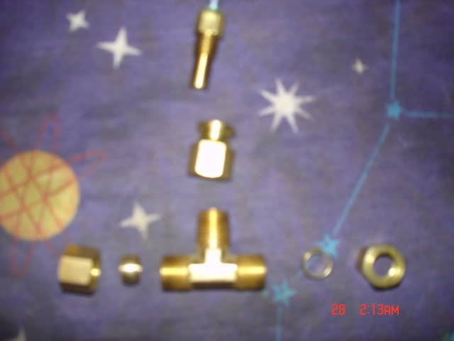
same idea, different set up.. i dont understand the little circle things with the bolts tho.. I dont get how thats supposed to go on? I think that this is telling me to cut the metal pipe as opposed to using the rubber line.. if i want to do the rubber line like you did what size is the T-fitting?
how much ATF should i expect to lose doing this?