4th Gen Manual Brake Conversion
 06-19-2016, 06:52 PM
#1
Registered User
Thread Starter

Join Date: Oct 2003
Location: Houston, TX
Posts: 16
4th Gen Manual Brake Conversion
I mocked up a prototype manual brake system on a 2000 Camaro. This system requires a 2.0” hole to be drilled in the firewall and a 31/64” hole to be drilled in the pedal. This swap is very similar to the 3rd gen f-body swap that I put together. The 3rd gen swap can be viewed in the link below.
Manual Brake Conversion with Pictures - Camaro Zone - Camaro Forums and News
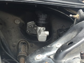
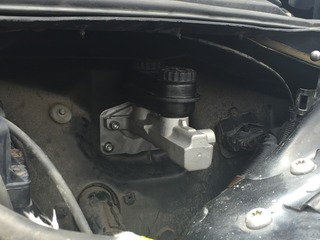
Here is the 2.0” hole drilled in the firewall between the upper holes of the vacuum booster bracket.

The 2.0” hole drilled in the firewall allows the use of the upper two holes that the brake booster bracket utilized and allows a master cylinder to bolt up.
This arrangement allows for a 6 to 1 pedal ratio. With a true 6 to 1 pedal ratio and using the upper bolt holes in the firewall, you also get good pushrod alignment with the master cylinder piston.
The 31/64” hole, that will be drilled into the brake pedal arm, is good for the ˝” stud/pin to be pressed into the pedal with an optimal interference fit with zero stud/pin play.
To utilize the ˝” stud/pin that is pressed into the brake pedal arm, I made a custom clevis with a ˝” hole for the stud/pin. The clevis is machined to use a 5/16” diameter pushrod with fine threads.
Here are the items used for the pushrod assembly.
A custom CNC aluminum plate was machined to cover up the original power booster hole and allow most GM, Ford, or Mopar style master cylinder to be utilized in the upper holes. A retention cup will also be fabricated and pressed into the plate to retain the pushrod so it doesn't fall out the back of the master cylinder.

Manual Brake Conversion with Pictures - Camaro Zone - Camaro Forums and News
Here is the 2.0” hole drilled in the firewall between the upper holes of the vacuum booster bracket.

The 2.0” hole drilled in the firewall allows the use of the upper two holes that the brake booster bracket utilized and allows a master cylinder to bolt up.
This arrangement allows for a 6 to 1 pedal ratio. With a true 6 to 1 pedal ratio and using the upper bolt holes in the firewall, you also get good pushrod alignment with the master cylinder piston.
The 31/64” hole, that will be drilled into the brake pedal arm, is good for the ˝” stud/pin to be pressed into the pedal with an optimal interference fit with zero stud/pin play.
To utilize the ˝” stud/pin that is pressed into the brake pedal arm, I made a custom clevis with a ˝” hole for the stud/pin. The clevis is machined to use a 5/16” diameter pushrod with fine threads.
Here are the items used for the pushrod assembly.
A custom CNC aluminum plate was machined to cover up the original power booster hole and allow most GM, Ford, or Mopar style master cylinder to be utilized in the upper holes. A retention cup will also be fabricated and pressed into the plate to retain the pushrod so it doesn't fall out the back of the master cylinder.


 06-19-2016, 06:55 PM
#2
Registered User
Thread Starter
Join Date: Oct 2003
Location: Houston, TX
Posts: 16
Re: 4th Gen Manual Brake Conversion
I did some measuring of the brake pedal assembly to find out what the stock power assist, vacuum booster pedal ratio would be. I also did the calculations of the manual brake system output at the master cylinder using different pedal ratios and master cylinder bore sizes.
Stock pedal length from center of pivot point to center of pedal pad is 12.0”
BOOSTED PEDAL RATIO
Distance from center of pivot point to center of power booster pin/stud location is 3.75”
12 ÷ 3.75 = 3.2 to 1 pedal ratio
MANUAL BRAKE PEDAL RATIO
On the F-body pedal, I moved the pin/stud location up on the pedal where it was 2.0” down from the pivot point.
12 ÷ 2 = 6 to 1 pedal ratio
I wanted to make sure my manual brakes have enough pedal ratio to create the greatest amount of leverage with roughly 1.0” of master cylinder piston travel. In this case, the 6 to 1 ratio worked out to be 1.0” (give or take a 1/16 of an inch).
After reading some of the other posts on their manual brake conversion, they moved the stud up 1.0” from the power boosted pin location.
12 ÷ 2.75 = 4.4 to 1 pedal ratio
For most brake systems, a 7/8” bore master cylinder will work well and create greater pressure than the larger 1.03” bore master cylinders.
Area of master cylinder bore:
• 7/8” bore master cylinder – 0.601 square inches
• 24mm bore master cylinder – 0.701 square inches
• 1-1/32” bore master cylinder – 0.836 square inches
If 100 pounds of pressure is applied to the brake pedal and a 6 to 1 pedal ratio:
• 7/8” bore master cylinder will create 998 psi of manual pressure
• 24mm bore master cylinder will create 886 psi of manual pressure
• 1-1/32” bore master cylinder will create 720 psi of manual pressure
If 100 pounds of pressure is applied to the brake pedal and a 4.4 to 1 pedal ratio:
• 7/8” bore master cylinder will create 732 psi of manual pressure
• 24mm bore master cylinder will create 628 psi of manual pressure
• 1-1/32” bore master cylinder will create 528 psi of manual pressure
VACUUM BOOSTED BRAKES PSI
If 100 pounds of pressure is applied to the brake pedal and a 3.2 to 1 pedal ratio:
• 24mm (stock size) secondary bore master cylinder will create 456 psi of manual pressure
• Area of a 9.0” dual diaphragm vacuum booster – 127.12 square inches
• 18 in Hg of vacuum converted to psi – 8.8 psi
• 127.12 square inches multiplied by 8.8 psi equals 1119 psi of vacuum boosted pressure
• 456 psi of manual pressure plus 1119 psi of vacuum boosted pressure is 1575 psi of pressure
Hopefully the vacuum boosted pressure is accurate. I am assuming that both diaphragms have the same area.
06-19-2016, 07:01 PM
#3
Registered User
Thread Starter
Join Date: Oct 2003
Location: Houston, TX
Posts: 16
Re: 4th Gen Manual Brake Conversion
Here are different views the finished manual brake adapter plate if looking at it from the engine bay side. A pushrod retention cup is added to make sure the pushrod does not fall away from the back of the master cylinder piston if brake fluid pressure is lost. The “bump” at the bottom of the adapter plate is to completely cover the hole that the brake booster bracket used.
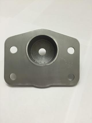
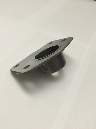
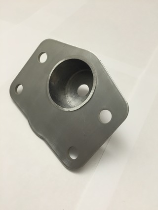
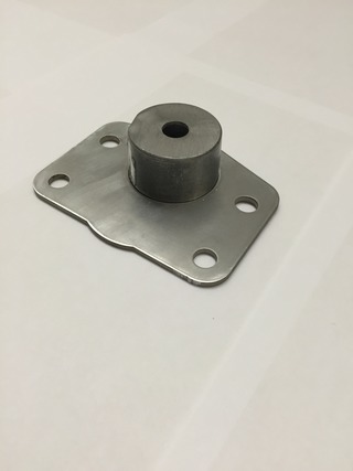
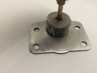
The below picture is the backside of the adapter plate that will mount against the firewall. The pushrod retention cup will install through the 2.0" hole drilled in the firewall.
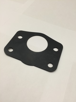
The below picture is the matching gasket for the manual brake adapter plate. The gasket will be sandwiched between the firewall after it is slid over the top of the retention cup in the above picture.
The below picture is the manual brake adjustable pushrod installed in the retention cup. The pushrod has provisions to keep it captured inside the pushrod retention cup. You would see this view from the engine bay before the master cylinder is installed and after you installed your adjustable pushrod assembly to the brake pedal arm.
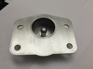
The below picture is the manual brake adjustable pushrod installed in the cup. You would see this view from under the dash after the adjustable pushrod assembly is installed on the brake pedal arm.
The below picture is the 1/2" thick aluminum firewall brace. It is installed under the dash, between the firewall and the brake pedal assembly bracket. The firewall brace is extended toward the driver side and bottom do take advantage of the stamped portion of the firewall. It significantly reduces firewall flex.
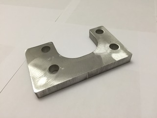


The below picture is the backside of the adapter plate that will mount against the firewall. The pushrod retention cup will install through the 2.0" hole drilled in the firewall.

The below picture is the matching gasket for the manual brake adapter plate. The gasket will be sandwiched between the firewall after it is slid over the top of the retention cup in the above picture.

The below picture is the manual brake adjustable pushrod installed in the retention cup. The pushrod has provisions to keep it captured inside the pushrod retention cup. You would see this view from the engine bay before the master cylinder is installed and after you installed your adjustable pushrod assembly to the brake pedal arm.

The below picture is the manual brake adjustable pushrod installed in the cup. You would see this view from under the dash after the adjustable pushrod assembly is installed on the brake pedal arm.

The below picture is the 1/2" thick aluminum firewall brace. It is installed under the dash, between the firewall and the brake pedal assembly bracket. The firewall brace is extended toward the driver side and bottom do take advantage of the stamped portion of the firewall. It significantly reduces firewall flex.

Last edited by malibudave; 11-22-2016 at 05:26 PM.
06-19-2016, 07:02 PM
#4
Registered User
Thread Starter
Join Date: Oct 2003
Location: Houston, TX
Posts: 16
Re: 4th Gen Manual Brake Conversion
Below is an analysis using the Brake Torque Calculator found on Pro-Touring.com. This calculator will give you an idea of what brake torque is for a certain front and rear setups. I am just going to show the changes from the stock, forth generation front "LT1" f-body brake system and compare them to a stock LS1 Camaro brake swap, a LS1 Camaro brake swap with Corvette calipers
Page 7, Post #140
Brake sizing and selection tutorial featuring Ron Sutton and Tobin of KORE3 - Page 7
This entire post is a really good read if you are interested about brakes.
Here are the inputs that are the same for ALL different types of brake systems shown below.
• 6 to 1 pedal ratio
• 26” tall tire
• 100 ft/lb pedal pressure
• Manual Brakes – NO POWER ASSIST
• Pad Coefficient of Friction - .45
• Use of stock type (tandem) master cylinder
__________________________________________________ __
Stock LS1 Camaro/Firebird Front Brake System
• Rotor Diameter – 12”
• 7/8” Bore Master Cylinder Area - .601 sq-in
• Line Pressure – 998 psi
• Front Caliper Piston Area – 4.931 sq-in
• Front Clamping Pressure – 4921 pounds
• Front Rotor Torque – 1107 ft/lb
• Tire Forces – 1022 lb
__________________________________________________ __
4th Generation “LT1” F-body Front Brake System
• Rotor Diameter – 10.94”
• 7/8” Bore Master Cylinder Area - .601 sq-in
• Line Pressure – 998 psi
• Front Caliper Piston Area – 4.909 sq-in
• Front Clamping Pressure – 4899 pounds
• Front Rotor Torque – 1006 ft/lb
__________________________________________________ __
Stock LS1 Camaro/Firebird Front Brake System with Corvette Calipers with 21mm bore master cylinder
• Rotor Diameter – 12”
• 21mm Bore Master Cylinder Area - .537 sq-in
• Line Pressure – 1117 psi
• Front Caliper Piston Area – 3.994 sq-in
• Front Clamping Pressure – 4461 pounds
• Front Rotor Torque – 1004 ft/lb
• Tire Forces – 927 lb
__________________________________________________ __
Stock G-body/S10/3rd Generation F-body Front Brake System
• Rotor Diameter – 10.5”
• 7/8” Bore Master Cylinder Area - .601 sq-in
• Line Pressure – 998 psi
• Front Caliper Piston Area – 4.909 sq-in
• Front Clamping Pressure – 4899 pounds
• Front Rotor Torque – 964 ft/lb
• Tire Forces – 890 lb
__________________________________________________ __
Stock LS1 Camaro/Firebird Front Brake System with Corvette Calipers with 7/8” bore master cylinder
• Rotor Diameter – 12”
• 7/8” Bore Master Cylinder Area - .601 sq-in
• Line Pressure – 998 psi
• Front Caliper Piston Area – 3.994 sq-in
• Front Clamping Pressure – 3986 pounds
• Front Rotor Torque – 897 ft/lb
• Tire Forces – 828 lb
Rating from best to worst:
1. LS1 Camaro / Firebird stock front brakes with 7/8" bore master cylinder.
2. LT1 Camaro / Firebird stock front brakes with 7/8” bore master cylinder.
3. LS1 Camaro / Firebird front brakes with Corvette brake calipers and a 21mm bore master cylinder. NOTE: A 21mm master cylinders are fairly rare and hard to find.
4. Stock g-body/S10/3rd Generation F-body stock front brake system with 7/8" bore master cylinder.
5. LS1 Camaro / Firebird front brakes with Corvette brake calipers and a 7/8” bore master cylinder.
05-10-2017, 01:05 PM
#6
Registered User
Thread Starter
Join Date: Oct 2003
Location: Houston, TX
Posts: 16
Re: 4th Gen Manual Brake Conversion
Master Cylinder Bleeding Procedures for a strait bore master cylinder.
NOTE: DO NOT bench bleed a master cylinder on the car. There may not be enough piston travel when bolted on the car. Use a vise to hold the master cylinder level to the ground to bleed the master cylinder of all its air.
I like to use plugs to bleed the master cylinder of air instead of the procedure that uses hoses to recirculate the fluid from the master cylinder ports back up to the reservoir.
Why?
When using plugs to close off the ports of the master cylinder, this procedure will let you know if all the air is out of the master cylinder AND if the master cylinder is bad. You don't want to find out your master cylinder is bad after you have it installed and are trying to bleed the rest of the system. You most likely will not get all the air out of the system when your master cylinder is bad. New or rebuilt, it is always good to make sure your master cylinder is in good working order before bolting it onto the car. It will be one less thing you have to trouble shoot if you run into other issues when you are trying to trouble shoot braking issues.
Steps to bleeding a master cylinder:
1. Mount the master cylinder in a vise with the bore of the master cylinder level with the ground. Do not use the top of the reservoir as a guide because is may not be level with the bore of the master cylinder. It may be at an angle versus the bore of the master cylinder.
2. Use the appropriate size solid plugs to plug the outlets of the master cylinder so no fluid can escape the ports.
3. Fill the master cylinder with the appropriate amount of brake fluid.
4. Use a rod to SLOWLY cycle the master cylinder piston in its bore. DO NOT use a flat head or phillips heat screwdriver because they have sharp edges and could harm the bore of the master cylinder. I usually use a nut driver that is used for Ľ” drive sockets as a rod because the end does not have any sharp edges and there is a handle to hold onto.
5. After cycling the master cylinder piston SLOWLY a few times, the piston should become rock solid and only move about 1/16 of an inch or less down the bore.
6. After the piston becomes rock solid, push in on the master cylinder piston and hold for 45 seconds. If the piston slowly moves down the bore of the master cylinder, you have a bad master cylinder. If the piston says rock solid and does not move, you master cylinder is good.
7. Mount to your car and bleed the rest of your system starting with the brakes furthest away (passenger rear) from the master cylinder and working your way to the closest (drivers front) brake.
06-28-2017, 01:05 PM
#8
Registered User
Thread Starter
Join Date: Oct 2003
Location: Houston, TX
Posts: 16
Re: 4th Gen Manual Brake Conversion
I pulled this information from the CPP website. I include this information on this thread because, during a manual brake conversion, the differential valve in the proportioning/combination valve may be triggered and cause only one side of the system to work resulting in poor braking performance.
The differential valve is built into most GM prop valves. It is for safety. If one side, front or rear, of the brake system looses pressure, the differential valve is triggered blocking off the low pressure side of the brake system so that the master cylinder can still provide pressure to the other side of the brake system. This ensures that there is some for of braking as a way to stop the vehicle. If a differential valve was not part of the braking system, and there is a loss of pressure in one side of the system, the master cylinder would not be able to build pressure. This would result in NO brakes.
Combination/Proportioning Valve Test
Use a test light by attaching a clip to a positive contact on the vehicle and touch the point of the tester to the electrical connection of the combination valve. If the the light does NOT come on, the valve system is operating correctly and no further testing is required.
If the light does come on, this indicates that the pressure differential valve is stuck in the front or rear position.
Bleed the brake system to determine if the front or rear lines are blocked off. Set up one front wheel and one rear wheel for bleeding at the same time. Crack both bleeder screws and gently pump the pedal a few times.
The blocked side will trickle fluid out when the bleeder screw is cracked and the pedal pressed. An unblocked line will squirt fluid out the bleeder.
The lines that are clear must be left open and the blocked lines should have the bleeder screws tight to cause pressure to build up on that side. Be sure to use the standard bleeding procedures to prevent air from entering the system.
Slowly press the pedal with steady pressure a number of times until the light goes out; this will center the differential valve. You may also hear a pop come from the proportioning valve. This is the metering valve returning to its equalized position. When the light goes out, close the bleeder screw. (See fig. below)
Attachment 2566

Thread
Thread Starter
Forum
Replies
Last Post
NewsBot
2010 - 2015 Camaro News, Sightings, Pictures, and Multimedia
0
05-29-2015 01:40 PM
NewsBot
2010 - 2015 Camaro News, Sightings, Pictures, and Multimedia
0
05-19-2015 05:00 PM
NewsBot
2010 - 2015 Camaro News, Sightings, Pictures, and Multimedia
0
05-18-2015 02:20 PM
NewsBot
2010 - 2015 Camaro News, Sightings, Pictures, and Multimedia
0
05-16-2015 03:40 PM
NewsBot
2010 - 2015 Camaro News, Sightings, Pictures, and Multimedia
0
05-15-2015 09:00 AM