95 LT1 Opti-Spark vacuum lines
 07-24-2014, 09:22 AM
#1
Registered User
Thread Starter

Join Date: Oct 2004
Location: Champlain, NY
Posts: 211
95 LT1 Opti-Spark vacuum lines
Since this 95 engine is going in a streetrod..couldn't the (2) opti-spark vacuum lines be combined as one? Right now one goes to the intake and the other to the throttle body boot.
Thanks
Thanks
Last edited by 4586; 07-24-2014 at 09:27 AM.
 07-24-2014, 11:08 PM
#3
Registered User

Join Date: Nov 2002
Location: Jacksonville
Posts: 4,784
 07-25-2014, 05:46 AM
#4
Registered User
Thread Starter
Join Date: Oct 2004
Location: Champlain, NY
Posts: 211
Re: 95 LT1 Opti-Spark vacuum lines
Are both lines vacuum from the opti & "into the engine" ?
Had if off and re-installed the plastic directional diaphram to allow vacuum from the opti into the intake..is this the correct flow?
thanks
Had if off and re-installed the plastic directional diaphram to allow vacuum from the opti into the intake..is this the correct flow?
thanks
Last edited by 4586; 07-25-2014 at 05:57 AM.
07-25-2014, 08:30 AM
#5
Administrator
Join Date: Nov 1998
Location: Hell was full so they sent me to NJ
Posts: 70,648
Re: 95 LT1 Opti-Spark vacuum lines
NO, not both "vacuum into the engine".
The line that attached to the inlet elbow is an air supply line. There is no (actually a very tiny) vacuum in front of the throttle blades. That air has passed through the MAF sensor (metered) and flows through the Opti, pulled through by the vacuum from the full vacuum port on the driver side of the intake manifold. The air flows into the combustion chambers, so metering it through the MAF sensor allows the PCM to add the fuel required for that air.
The line from the Opti to the intake manifold has a check valve, to prevent a backfire in the intake manifold from pressuring the Opti, and a restriction orifice to limit the air flow under conditions of high vacuum, which in turn, limits the vacuum applied to the Opti housing. Too much vacuum and it could deform the cap and force it into the rotor.
The purpose of the air flow is to remove the ozone created by the high voltage discharge from the rotor tip to the cap buttons. Ozone is highly corrosive.
As usual, Shoebox has the info you need:
http://shbox.com/1/opti_vacuum_hose.jpg
Last edited by Injuneer; 07-25-2014 at 08:32 AM.
07-25-2014, 10:46 AM
#6
Registered User
Thread Starter
Join Date: Oct 2004
Location: Champlain, NY
Posts: 211
Re: 95 LT1 Opti-Spark vacuum lines
Thanks
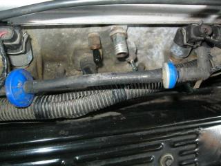
I removed the blue/white check valve to install a small elbow as seen in the picture. So my directional guess was correct.
Getting ready to clean the engine before install and eliminating as many hoses/connectors that I can.
Looks like I'm good to go. Again..thanks
I removed the blue/white check valve to install a small elbow as seen in the picture. So my directional guess was correct.
Getting ready to clean the engine before install and eliminating as many hoses/connectors that I can.
Looks like I'm good to go. Again..thanks
 07-26-2014, 11:45 AM
#7
Registered User
Thread Starter
Join Date: Oct 2004
Location: Champlain, NY
Posts: 211
Re: 95 LT1 Opti-Spark vacuum lines
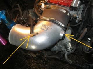
One last question on vacuum lines. I was given a TF8-LT1C aluminum elbow (free) that I would like to use. The IAT will mount in the existing hole...where have you guys w/this elbow mounted the opti vacuum line? Possibly tap into the rubber connector?

Last edited by 4586; 07-28-2014 at 07:13 AM.
07-26-2014, 12:50 PM
#8
Administrator
Join Date: Nov 1998
Location: Hell was full so they sent me to NJ
Posts: 70,648
Re: 95 LT1 Opti-Spark vacuum lines
I'm not familiar with that elbow, so I don't know what the "rubber connector" is. Picture is not clear. Since the elbow is turned upside down in the photo, it would appear that the connection you reference is on the bottom. I can't think of anything else that would connect to the elbow, other than the Opti vent line. As long as the connection point is between the MAF sensor and the throttle blades, you will be fine. You could even insert it into the rubber coupling, with a bit of RTV to seal it.
07-26-2014, 09:36 PM
#9
Registered User
Join Date: Nov 2002
Location: Jacksonville
Posts: 4,784
Re: 95 LT1 Opti-Spark vacuum lines
Most of the metal elbows have a small port on the bottom where you can insert a plastic 1/8" (I think) vacuum fitting for the opti air supply. I don't see one on that one. Drilling & tapping a hole for a fitting into the bottom of the elbow is probably going to be your best bet. Putting the fitting in the silicone or rubber connectors would also work but you run into interference with the ends of the elbow/MAF if the couplers aren't long enough.
07-27-2014, 06:55 AM
#10
Registered User
Thread Starter
Join Date: Oct 2004
Location: Champlain, NY
Posts: 211
Re: 95 LT1 Opti-Spark vacuum lines
Most of the metal elbows have a small port on the bottom where you can insert a plastic 1/8" (I think) vacuum fitting for the opti air supply. I don't see one on that one. Drilling & tapping a hole for a fitting into the bottom of the elbow is probably going to be your best bet. Putting the fitting in the silicone or rubber connectors would also work but you run into interference with the ends of the elbow/MAF if the couplers aren't long enough.
Will do that once the engine is in the car (37 Chevy) since we aren't sure how the air plumbing will be routed.
My next post will be asking how to plumb the cooling system using a typical (2) hose radiator with inside heater core. ie height of reservoir, T fittings etc. There is plenty of room inside the engine compartment of the 37 Chevy sedan and with (3) water lines on each side of the LT1 water pump..I'm lost.
THANKS GUYS!
07-27-2014, 09:51 AM
#11
Administrator
Join Date: Nov 1998
Location: Hell was full so they sent me to NJ
Posts: 70,648
Re: 95 LT1 Opti-Spark vacuum lines
Auto or manual trans - affects the radiator choice/plumbing? Factory LT1 oil cooler, or no oil cooler - ditto? Do you plan to keep the coolant connected to the throttle body, or delete it (recommended)? You must keep the coolant lines that connect to the back of the heads, and that line connects to a liquid/vapor separator built into the stock radiator.
Note that the LT1 circulates coolant through the heater core at all times, and uses a restriction fitting to control the flow.
Review Shoebox's coolant and heater plumbing diagrams, if you haven't already:
http://shbox.com/1/93-94_hoses.jpg
http://shbox.com/1/heater_hoses_93-94.jpg
http://shbox.com/1/95-97_hoses.jpg
http://shbox.com/1/heater_hoses.jpg
http://shbox.com/1/oil_cooler.jpg
You might want to check into the flow diagrams for the Corvette LT1 cooling system. It is much better, and "self-bleeds" air from the system.
http://www.carcraft.com/techarticles...photo_02.html#
Last edited by Injuneer; 07-27-2014 at 09:58 AM.
07-27-2014, 12:16 PM
#12
Registered User
Thread Starter
Join Date: Oct 2004
Location: Champlain, NY
Posts: 211
Re: 95 LT1 Opti-Spark vacuum lines
Fred
Running the stock 4L60E with cooling lines to radiator.
Car didn't have engine oil cooler setup (95 Camaro convertible)
Didn't save the heater core line restricter fitting..have any idea what the restriction diameter is? Can make one on my lathe.
I have a subscription to CarCraft but can't locate that January 2008 LT1 info issue..can pick it up on ebay.
No problem by-passing the throttle body? (Sounds good to me).
Ed
07-27-2014, 04:07 PM
#13
Administrator
Join Date: Nov 1998
Location: Hell was full so they sent me to NJ
Posts: 70,648
Re: 95 LT1 Opti-Spark vacuum lines
The Car Craft article is available online. That's where the link came from:
Gen II Chevy Small Block Engine - Build Some Power With A '92-'96 Gen II LT1 - Car Craft Magazine
No idea what the diameter of the restriction orifice is. Maybe Rob/Shoebox knows.
Gen II Chevy Small Block Engine - Build Some Power With A '92-'96 Gen II LT1 - Car Craft Magazine
No idea what the diameter of the restriction orifice is. Maybe Rob/Shoebox knows.
07-28-2014, 07:31 AM
#14
Registered User
Thread Starter
Join Date: Oct 2004
Location: Champlain, NY
Posts: 211
Re: 95 LT1 Opti-Spark vacuum lines
To verify throttle body coolant delete procedure:
1) the small coolant line from the back of the head (pass side) to the lower throttle body is redirected instead to the radiator (by-passing TB).
2) The typical streetrod radiator has no provision for the redirected line....where would one tap it into a non LT1 cooling system? Found a posting on another forum where the guy tapped into a heater hose line.
3) Is there any concerns with using a standard flow aftermarket radiator as a reverse flow?
Thanks
Last edited by 4586; 07-28-2014 at 08:53 AM.

Thread
Thread Starter
Forum
Replies
Last Post
dbusch22
Forced Induction
6
10-31-2016 11:09 AM
crazypurgatory
General 1967-2002 F-Body Tech
2
01-12-2015 10:45 PM