Vacuum Line Diagram and routing
 07-10-2014, 03:50 PM
#1
Registered User
Thread Starter

Join Date: Jul 2014
Posts: 6
Vacuum Line Diagram and routing
Wassup Camaro fans. Does anybody know where I can the correct vacuum lines diagram and routing for a 93 Z28 Camaro LT1? In the midst of restoring my car and have broken vacuum lines but don't know where they go. NEED HELP! 😩🙏
 07-10-2014, 07:15 PM
#2
Administrator
Join Date: Nov 1998
Location: Hell was full so they sent me to NJ
Posts: 70,646
Re: Vacuum Line Diagram and routing
Is the vacuum diagram still on the radiator cover? That will be specific to your 93, which has a few differences compared to 94 and up.
You can try shbox.com, but his photos are of a 95. If all else fails, I can give you a link to a free download of the 93 factory manual.
You can try shbox.com, but his photos are of a 95. If all else fails, I can give you a link to a free download of the 93 factory manual.
07-11-2014, 07:18 AM
#3
Registered User
Thread Starter
Join Date: Jul 2014
Posts: 6
Re: Vacuum Line Diagram and routing
Is the vacuum diagram still on the radiator cover? That will be specific to your 93, which has a few differences compared to 94 and up.
You can try shbox.com, but his photos are of a 95. If all else fails, I can give you a link to a free download of the 93 factory manual.
You can try shbox.com, but his photos are of a 95. If all else fails, I can give you a link to a free download of the 93 factory manual.
07-11-2014, 11:10 PM
#4
Administrator
Join Date: Nov 1998
Location: Hell was full so they sent me to NJ
Posts: 70,646
Re: Vacuum Line Diagram and routing
LINK: 4TH GEN SERVICE MANUALS; 82-02 PARTS DIAG; 99-02 WIRING DIAG - Firebird Nation
The label on the radiator cover would look like this (but this one is for a 95):
Courtesy of Shoebox
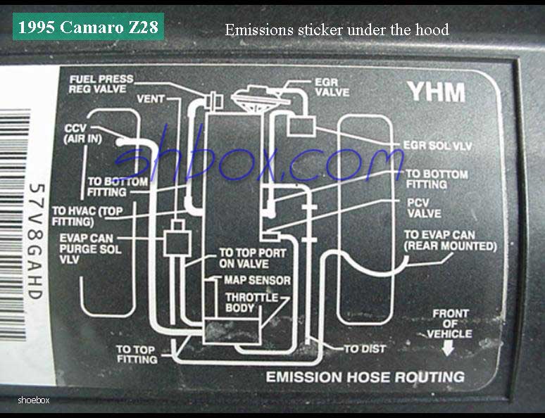
On your 93, the fuel pressure regulator is in a slightly different position, the PVC hose is different (same as 94) and you will not have the line that shows "to dist".... that's for the vented Optispark, that was used 95 and up.
The label on the radiator cover would look like this (but this one is for a 95):
Courtesy of Shoebox
On your 93, the fuel pressure regulator is in a slightly different position, the PVC hose is different (same as 94) and you will not have the line that shows "to dist".... that's for the vented Optispark, that was used 95 and up.
07-12-2014, 05:23 PM
#5
Registered User
Thread Starter
Join Date: Jul 2014
Posts: 6
Re: Vacuum Line Diagram and routing
LINK: 4TH GEN SERVICE MANUALS; 82-02 PARTS DIAG; 99-02 WIRING DIAG - Firebird Nation
The label on the radiator cover would look like this (but this one is for a 95):
Courtesy of Shoebox
On your 93, the fuel pressure regulator is in a slightly different position, the PVC hose is different (same as 94) and you will not have the line that shows "to dist".... that's for the vented Optispark, that was used 95 and up.
07-12-2014, 05:33 PM
#6
Administrator
Join Date: Nov 1998
Location: Hell was full so they sent me to NJ
Posts: 70,646
Re: Vacuum Line Diagram and routing
No. Your Opti is "unvented" and doesn't have a vacuum connection. But the vacuum connection for your PCV valve is not under the throttle body. There is a U shaped hose thar goes from the PCV to one of the vacuum ports a few inches behind the PCV. I'll post a pic later when I'm not on my phone.
07-15-2014, 06:41 AM
#7
Registered User
Thread Starter
Join Date: Jul 2014
Posts: 6
Re: Vacuum Line Diagram and routing
No. Your Opti is "unvented" and doesn't have a vacuum connection. But the vacuum connection for your PCV valve is not under the throttle body. There is a U shaped hose thar goes from the PCV to one of the vacuum ports a few inches behind the PCV. I'll post a pic later when I'm not on my phone.
07-15-2014, 12:01 PM
#8
Administrator
Join Date: Nov 1998
Location: Hell was full so they sent me to NJ
Posts: 70,646
Re: Vacuum Line Diagram and routing

Looking at the connections:
-top, right is the brake booster vacuum line.
-below the brake booster, slightly to the right of it, is the vacuum connection for the "U" shaped line from the PCV valve - you can't see the actual connection in the picture.
-top, left is the connection for the EGR vacuum hose. Mine as a second line tee'd into it, because I converted to a vented Opti. On yours, the 90-deg elbow from the EGR hose will go directly to the nipple on the intake manifold.
-below the EGR connection is a grommet for the PCV valve. The valve sticks into a passage that connects to the lifter valley at the bottom of the intake manifold.
This shows the line from the upper connection on the passenger side of the throttle body to the passenger side valve cover:

Shoebox shows the connections on the passenger side of the intake - vacuum for: HVAC, fuel pressure regulator, EVAP purge
http://shbox.com/1/evap_sol.jpg

Thread
Thread Starter
Forum
Replies
Last Post
carguyshu
Parts For Sale
20
01-22-2017 11:19 AM