Mid-Lift Valvetrain Geometry w/Rocker Studs
 05-24-2008, 10:31 AM
#1
Registered User
Thread Starter
Join Date: Jan 2004
Location: Downey, CA
Posts: 1,406
Mid-Lift Valvetrain Geometry w/Rocker Studs
I'm not sure why I did not think to put this up on the advanced tech board, it just did not dawn on me. I've put some posts up on the general tech board and had a mix of replies. I'll probably swap out my studs, guideplates, and pushrods on Monday and wanted to see if there were any more comments on this. The current plan is in the following thread and is to swap 7.05" pushrods with 7.30" pushrods.
https://www.camaroz28.com/forums/sho...d.php?t=599108
The mid lift research and prior discussion is in this thread> https://www.camaroz28.com/forums/sho...d.php?t=594453
I'd be interested in any additional comments, and in particular comments related to what will actually happen when .100" of centered sweep across the valve is reduced to about .040" of sweep off center towards the exhaust side. I tend to think of the valve as rigid column and within reason, pushing down off-center should not have any negative impacts regarding valve guide wear. I would think more sweeping motion, regardless of where it occurs (within reason again) on the tip of the valve stem is worse than less sweeping in terms of wear.
Thanks in advance for any feedback.
 05-24-2008, 03:05 PM
#2
Registered User
Join Date: Aug 2005
Location: Kantuckee Yo'
Posts: 4,405
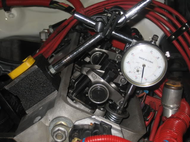
After having to some more work on my motor, I spent some more time playing around with rocker geometry. I have been anxious to see what effect pushrod length has on sweep and gross valve lift. I rigged up a dial indicator to measure gross lift and went to down with an adjustable pushrod.
Here is what I found:
Gross valve lift is my exhaust lobe lift multiplied by 1.6
7.000" PR provided additional .009" gross valve lift over cam card spec
7.050" PR provided additional .011" gross valve lift over cam card spec
7.100" PR provided additional .014" gross valve lift over cam card spec
7.150" PR provided additional .016" gross valve lift over cam card spec
7.200" PR provided additional .018" gross valve lift over cam card spec
7.250" PR provided additional .021" gross valve lift over cam card spec
7.300" PR provided additional .024" gross valve lift over cam card spec
7.350" PR provided additional .026" gross valve lift over cam card spec
7.400" PR provided additional .029" gross valve lift over cam card spec
7.450" PR provided .032" gross valve lift over cam card spec
Clearly the longer the pushrod got, the more gross valve lift was generated. I never saw the lift max out or fall but I stopped at 7.450" pushrod length.
Regarding sweep. The 7.000" gave dead centered sweep but measured ~.095" wide. I am going to change to 7.150" pushrods which will reduce sweep to ~.070" and increase lift by .007". The 7.200" sweep is too far to the exhaust side for my comfort.
I think when it all comes out in the wash. There are minuscule gains in lift to be had at the expense of moving the sweep pattern off centered a bit. I imagine there are minuscule reductions in parasitic drag by reducing the sweep and the distance the roller tip has to roll.
The only thing I can say IMHO is that the LT1 geometry will never be perfect with stud mounted rockers. To me perfect would be max lift coupled with narrow and centered roller sweep. There are clearly compromises that have to be considered and I further feel mid-lift is impossible without spending major bucks. Just want to pass along my results.
Here is the way I took the measurements:
05-24-2008, 08:48 PM
#3
Registered User

Join Date: Oct 2007
Posts: 220
What I think was happening is that you were converting the longer valve sweep to more valve lift as you increased the pushrod length. The cam has only so much lift on the lobe. The lift is wasted if it is used up in the sweep. So the less sweep the more lift.
From what I have been told as long as the sweep is within 25% of the valve stem diameter from the edge of the valve you are OK. That is what I have done and wound up with a pushrod 7.365" in length for my situation. My sweep is .041". The minimum sweep I got was around .031" but that was to close to the edge of the valve for my taste and certainly beyond the 25% rule.
I noticed that Crower makes a roller rocker that has the fulcrum set back .090". Probably for the reason you found out. It would keep the rocker more centered on the valve stem when approaching mid-lift on a rocker stud system.
05-27-2008, 12:37 AM
#5
Registered User
Thread Starter
Join Date: Jan 2004
Location: Downey, CA
Posts: 1,406
Your measurements are probably good relative to one another, but as stated previously, the lift is a fixed maximum. The relative gains are the conversion of sweep to lift and duration as you increase pushrod length.
I finished installing the 7.30" pushrods and related hardware today. I did the play-doh test for the polylock to cover and it's really close, but clears by a hair. I'm also right at that 25% from the edge of the valve stem tip (about .08"). I'm not sure where I ended up with the sweep, but it should be about half of what it was before.
Another thing is I confirmed that the ARP sealant is no good for rocker studs on ported heads. I had oil on the intake stud threads, which I suspected based on feedback from another post. And this is with only about 300 miles on them. I cleaned everything up really well and used Permatex #2 this time around.
05-27-2008, 06:30 AM
#6
Registered User
Join Date: Aug 2005
Location: Kantuckee Yo'
Posts: 4,405
Snap some photos of the sweep patterns and post them with the new measurements. BTW I found that a dry erase marker is the absolute best thing for checking rocker geomentry. Its is way better than the sharrpie or gear marking compond I have used in the past.
05-27-2008, 09:35 AM
#7
Registered User
Thread Starter
Join Date: Jan 2004
Location: Downey, CA
Posts: 1,406
I'll put up a couple of photos after work. I only took pictures of #1 I and E. I'll also start it up after work today. I wanted to give the Permatex #2 a day to dry.
 05-27-2008, 10:54 PM
#11
Registered User
Thread Starter
Join Date: Jan 2004
Location: Downey, CA
Posts: 1,406
You need to read the mid lift information. If you consider the valve opening and closing motion as up and down then sweep is left to right. Because the motion of the rocker is an arc it moves both up and down and left to right.
Posting the pics of #1 I and E will have to wait a couple more days. I can't get to it right now.
I forgot to add that everything started and ran fine with the new valvetrain parts. On the first test drive valvetrain seemed a tad quieter and the car ran strong. My wife says it feels smoother, but I could not really tell. It's a very minor, yet noticable inprovement. Hopefully the off center roller rocker contact with the tip of the valve stem will result in equal or less wear than the previous condition. It all sounds good on paper so we will see how it plays out.
Last edited by truedualws6; 05-28-2008 at 11:12 AM.
05-31-2008, 12:31 AM
#13
Registered User
Thread Starter
Join Date: Jan 2004
Location: Downey, CA
Posts: 1,406
Photo of Sweep Pattern


Thread
Thread Starter
Forum
Replies
Last Post